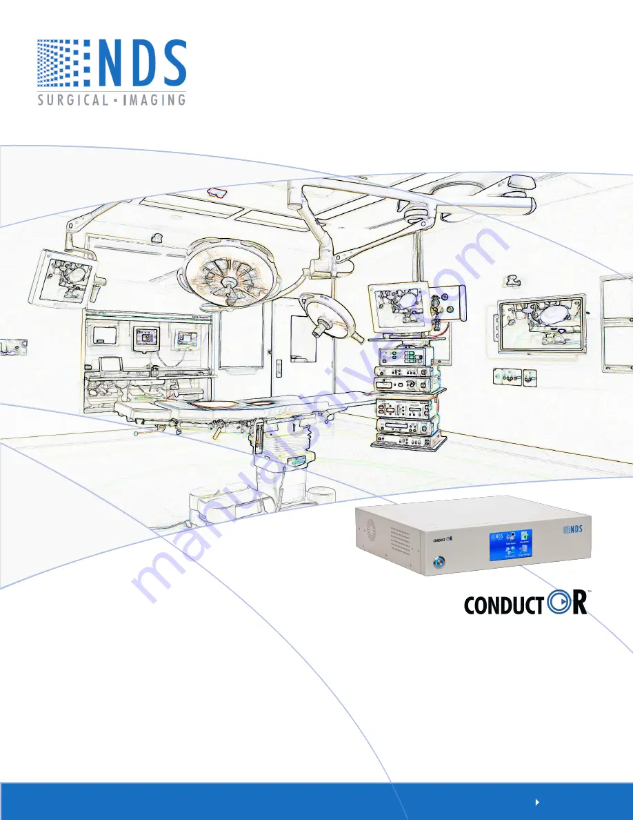
NDS ConductOR User Manual Download Page 1

User manUal

[ E N g l I s H ]

Asia Pacific Offices

1st Fl., rIse Building, 5-13, 
asakusabashi 5-Chome,
Taito-Ku, Tokyo,  Japan, 111-0053 
Tel: + 81 3 6420 3031
email: [email protected]

OR Informatics System

Summary of Contents for ConductOR

Page 1: ...User manual E n g l i s h OR Informatics System...

Page 2: ......

Page 3: ...oducts from other vendors does not imply any recommendation or endorsement This document contains proprietary information protected by copyright No part of this manual may be reproduced by any mechani...

Page 4: ......

Page 5: ...0 VGA SOG Picture Menu 21 RGBS YPbPr Picture Menu 21 DVI Picture Menu 22 Color Menu 23 Setup Menu 24 Defaults Menu 24 Tab 8 Utilities 25 Tab 9 Streaming Video Audio 26 Location to Location Network Con...

Page 6: ...ity of the installer to ensure that the equipment is installed in accordance with applicable hospital local and national electrical codes An equipotentiality post located on the back of the equipment...

Page 7: ...propriate they reserve all patent copyright and other proprietary rights to this document including all design manufacturing reproduction use and sales rights thereto except to the extent said rights...

Page 8: ...pment When video source equipment is connected to the ConductOR the end user must verify that video is passed from the video source through the ConductOR and is displayed correctly on the connected mo...

Page 9: ...720p or greater resolution 3 HD displays with HD SDI or 3G SDI input Control Options The ConductOR may be controlled from 1 Its front LCD touch panel 2 A PC via the RS 232 port See page 50 for serial...

Page 10: ...in receive mode YPbPr OUT outputs the video data that is inbound to the streamer This data may viewed by selecting LAN as the input for the active display See Select Input Screen on page 10 and Primar...

Page 11: ...ntial Equalization Conductor Power Switch The power switch is push on push off When the switch is off the ring around the center portion is white When the switch is on the center portion is depressed...

Page 12: ...installed in any of the OUT see page 3 card slots in any combination and in any order Up to four output modules may be installed 2 The DVI D and Fiber Optic output modules output signals of 1280 x 720...

Page 13: ...le Removal Use a number 1 Phillips screwdriver to loosen but not remove the screws located on the left and right sides of the module s mounting plate When the screws are clear of the chassis remove th...

Page 14: ...r Fiber USB or RS 232 Touch Screen Control RS 232 Control 1 2 3 4 This monitor displays the same information as monitor 3 PC Video Out 3G SDI DVI or Fiber 3G SDI DVI or Fiber 3G SDI DVI or Fiber DVI O...

Page 15: ...wer is applied to the ConductOR and is displayed until the ConductOR s Power On Self Test POST finishes The POST takes approximately 20 seconds to complete After the POST finishes the home screen is d...

Page 16: ...ctOR The user may restore the ConductOR s factory defaults or update the scalar firmware Touch this icon to open the Information screen shown on page 14 IP Streaming This screen is associated with net...

Page 17: ...Touch the Go Back button to return to the home screen Touching the Identify button displays a 1 2 or 3 on the monitor connected to the corresponding output Note As output 4 is slaved to output 3 a 3 w...

Page 18: ...ut screen is the current input Select a Primary input by touching the button associated with that input To select a secondary input touch the Change button on the Secondary row A grayed out button on...

Page 19: ...ges Each time the PIP button is touched the PIP icon changes as you cycle through the PIP sizes Touch the Swap button to exchange the text in the Primary and Secondary rows The primary and secondary i...

Page 20: ...u or parameter you want work with The Brightness Contrast button usage is detailed on page 18 Touch the Go Back button to return to the Select Inputs screen Changes made via the keypad are retained wh...

Page 21: ...set to 1200 Touch the Go Back button to return to the Home screen Touch the Output Settings icon on the home screen page 9 to display the Display Output Settings screen Information Screen Touch the In...

Page 22: ...splay 3 to select the output whose data will be sent to the network Set Stream Resolution to 1080i 720p or 480p to match the receiving device s capabilities The IP Address may be set via DHCP default...

Page 23: ...conds Displays connected to OUT 3 and OUT 4 will show a 3 On the Select Display row touch the Display 1 icon Display 1 is used for illustration On the Primary row touch the Change button The Primary I...

Page 24: ...ime will restore the inputs to their original locations It is not necessary for both images to be displayed in order to swap primary and secondary images Turn the PIP image off by touching the Disable...

Page 25: ...ts display icon Touch this button to return to the Select Inputs screen page 16 Touch the Brightness Contrast button to display the Brightness control menu Touch the fi or fl button to adjust Primary...

Page 26: ...ut s primary input is shown in black at the top left of the OSD If there is an active secondary input it will be shown in gray at the top right of the OSD The four available OSD menus are Picture Colo...

Page 27: ...the sharpness focus of the displayed image Overscan 0 The image is displayed at a size that fills the screen without losing any video information The image presented to the display may include black b...

Page 28: ...and bottom or the left and right of the image 1 1 Displays the video data in its native size and aspect ratio Image may be displayed with black bars on the top and bottom and on the left and right Se...

Page 29: ...r left and right Select using fi or fl buttons Scaling Graphics This parameter is enabled when the input is graphics computer data Fill Expands the video image to fill the entire screen The aspect rat...

Page 30: ...User allows the individual adjustment of the Red Green and Blue values Red Green Blue Video or Graphic modes Touch the fi or fl button to increase or decrease the intensity of the selected color Satur...

Page 31: ...ConductOR Auto Source Select This function is not supported on the ConductOR Menu Lock The menu may be locked via an external control program Operating Hours This function is not supported on the Cond...

Page 32: ...g training installation and troubleshooting They may not be used during clinical procedures Place the supplied Integration Software and Users Manual CD 58E0017 in your PC s CD or DVD drive and double...

Page 33: ...ouble click its folder Double click the Setup icon Follow the on screen instructions Repeat steps 3 and 4 for each additional software package you want to install E ConductOR 58D0013 B_View OR G2 View...

Page 34: ...munication Video transmitted from the ConductOR designated as Transmit and video viewed on the ConductOR designated as Receive The audio is bidirectional allowing the staff at each location to convers...

Page 35: ...ur IP network and powered on the network will automatically assign it an IP address via its Dynamic Host Configuration Protocol DHCP feature Connect an RS 232 cable from your PC to the ConductOR s RS...

Page 36: ...tton A successful connection will gray out the Connect button fill in the IP Address Subnet Mask and Gateway windows A dot appears in the radio button to the left of Use the following static IP addres...

Page 37: ...se the ConfigOR G2 program Move the RS 232 cable back to the Transmit unit s RS 232 IN connector page 30 Launch the ConfigOR G2 program select the COM port to be used then click the Connect button Typ...

Page 38: ...ion 1080i 720p or 480p The IP address is displayed in the IP Address row window should be the same as the IP address that was assigned when you ran the ConfigOR G2 program page 29 Touch the IP Streami...

Page 39: ...32 Touch the Start button The legend on the button changes to Stop The Connecting to screen is displayed When the Connected screen is displayed streaming has started Continued on the next page...

Page 40: ...changes to green when an connection is established The Receive unit s Remote IP window remains empty Touch the Stop button to stop streaming data to the Receive unit Note If the Transmit unit s IP add...

Page 41: ...isplay On the Home screen page 9 touch the Select Inputs icon Verify that the resolution of the selected output is 1080 See page 14 On the Select Display row touch the Display 1 icon On the Primary ro...

Page 42: ...he Select Display row touch the Display 1 icon On the Primary row touch the Change button The Primary Input screen is displayed Touch the LAN button Finally touch the Go Back button to return to the S...

Page 43: ...AUDIO OUT connector of both units Speak into the microphone connected to the Transmit unit and you should hear your voice in the headphones connected to the Receive unit Now speak into the microphone...

Page 44: ...geon performing the procedure may need to consult with one or more colleagues at other locations If the colleagues have a PC Internet connection and ViewOR available they will be able to observe the p...

Page 45: ...it s DVI 2 input Connect the unit s OUT 1 see connector panel on page 3 to a compatible display Finally on the Home screen page 9 touch Select Inputs icon On the Select Display row touch the Display 1...

Page 46: ...ming icon on the Home screen page 9 to access the IP Streaming screen On the Mode row touch the Transmit button Select Display 1 on the Stream Source row Select 720p on the Stream Resolution row Touch...

Page 47: ...be shown in its lower left corner Click the down pull arrow on the right side of the COM Port window and select the COM port to be used Finally click the Connect button A successful connection will g...

Page 48: ...e ViewOR G2 icon to launch the program Click the fl button the Open Media window is displayed Click the Open Media window s Network tab Select RTSP from the Protocol pull down menu Type the IP address...

Page 49: ...It takes up to 15 seconds before an image is displayed Record the video by clicking the record button the record button starts flashing Recording stops when the record button is clicked again Default...

Page 50: ...pears Call Connected appears when the audio connection is established Place the cursor over the Volume slider hold the left mouse button down and set the volume to the desired level The PC s microphon...

Page 51: ...in the User Name window and its password in the Password window Finally click the Add button to save the name and password A single user name may be removed by selecting the name in the User List then...

Page 52: ...1024 or larger monitor Click the Windows Start button then click All Programs Select NDS Surgical Imaging then select and click DemoOR G2 to launch the demonstration program The program s startup scr...

Page 53: ...talled Clicking the Identify button displays a 1 2 or 3 in yellow on each of the monitors connected to the ConductOR The monitor connected to OUT 4 will display a 3 The program s Help file may be view...

Page 54: ...ry input may be selected by clicking one of the Secondary Inputs buttons A graphic showing the size of the secondary PIP window will appear in the active display The size of the PIP window is controll...

Page 55: ...signal connected to it Touch the Select Inputs icon page 9 then on the Select Inputs screen touch the Identify button If the module s ID is displayed on one of the connected displays then select an i...

Page 56: ...om a PC connected to the same network as the ConductOR click the start button then select All Programs Accessories Command Prompt 4 Type ping and the IP address from the IP Address window The response...

Page 57: ...OK Click File click Properties then select ASCII Setup from the Properties menu In the ASCII Setup menu select Echo typed characters locally Click OK to exit ASCII Setup Click OK to exit configuration...

Page 58: ...51 Drawing and Dimensions 11...

Page 59: ...ompliant with DVI 1 0 PIN SIGNAL PIN SIGNAL 1 T M D S DATA 2 16 HOT PLUG DETECT 2 T M D S DATA 2 17 T M D S DATA 0 3 T M D S DATA 2 4 SHIELD 18 T M D S DATA 0 4 T M D S DATA 4 19 T M D S DATA 0 5 SHIE...

Page 60: ...ID N C 4 GND Ground USB Connector Serial Control Pin Name Description 1 NC No Connection 2 RXD Data Receive 3 TXD Data Transmit 4 NC No Connection 5 GND Ground 6 NC No Connection 7 NC No Connection 8...

Page 61: ...de of the U S should adhere to the applicable electrical codes for their country 24 Volt Extension Cables The cable requires one each of the following connectors Switchcraft SL403F female and Weidmull...

Page 62: ...und Sleeve Fuse Replacement 1 Disconnect the power cord from the ConductOR 2 Using a small screwdriver at point A pry the Fuse Box out 3 Replace the fuse with a Buss T5AL 250V or equivalent 4 Slide th...

Page 63: ...p VGA Input signal level at 75Ohms 0 7 V p p HD SDI Input signal level 8 to 2 0 V p p S Video Input signal level 0 7 V p p Composite Input signal level 0 7 V p p Sync On Green SOG 0 7 V p p RGBS Input...

Page 64: ...1080 60p RGBS YPbPr DVI SDI 67 300 Progressive 16 9 SMPTE 274M Video and Graphics Inputs Connector Type Composite BNC 75 Ohm terminated VGA Sync On Green SOG HD 15 DVI RGBS YPbPr DVI I Input Modules D...

Page 65: ......

Page 66: ...enue San Jose CA 95138 S Tel 408 776 0085 E mail info ndssi com Asia Pacific Takanawa Kaneo Bldg 6F Asakusabashi 5 Chome Minato ku Tokyo 108 0074 Japan Tel 81 3 5475 1835 Email info ndssi jp E Europe...

Reviews: