


6-20 Chapter 6: Installing Optional Remote Peripherals
6.
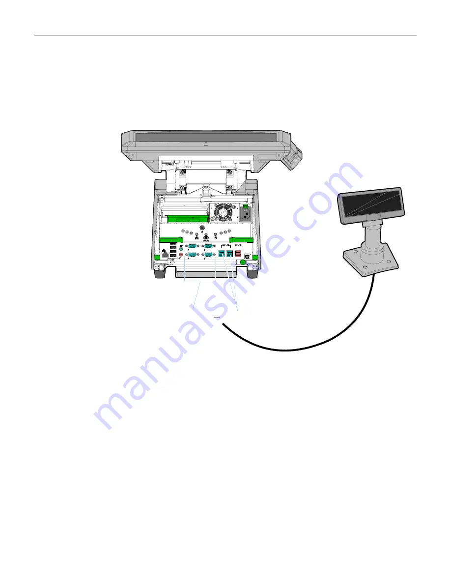
Connect
the
Display
Cable
to
the
terminal,
based
on
the
type
of
interface
you
are
using.
USB Interface (Powered)
Connect
the
I/F
cable
to
a
powered
12V
Powered
USB
connector
on
the
terminal.
26243
A B C
D E
F
E
F
G
RS232/ B
RS232/ D
RS232/ A
RS232/ C
MIC
Line Out
A
B
C
D
LAN
Cash
Drawer
Powered RS-232
12V USB
or
RS-232 Interface (Powered)
Connect
the
I/F
cable
to
a
powered
RS
‐
232
connector
on
the
terminal.
Note:
The
factory
settings
for
the
COM
ports
are
non
‐
powered
by
default.
To
change
a
port
to
powered
see
the
Circuit
Boards
chapter
in
the
NCR
RealPOS
70
XRT
Service
Guide
,
B005
‐
0000
‐
1874.
Configure
the
terminal
serial
port
as
follows:
•
9600
baud
•
8
data
bits
•
1
start
bit
•
No
parity
•
1
stop
bit
•
Half
‐
Duplex
Summary of Contents for RealPOS 70XRT
Page 1: ...NCR RealPOS 70XRT 7403 POS Workstation Release 1 2 User Guide B005 0000 1872 Issue E ...
Page 80: ...4 6 Chapter 4 Installing a Secondary Dual Display ...
Page 124: ...7 10 Chapter 7 Installing a RAID System ...
Page 129: ...Chapter 8 2x20 Customer Display Interface 8 5 CP437 ...
Page 130: ...8 6 Chapter 8 2x20 Customer Display Interface CP858 ...
Page 131: ...Chapter 8 2x20 Customer Display Interface 8 7 CP866 ...
Page 132: ...8 8 Chapter 8 2x20 Customer Display Interface CP932 ...
Page 134: ...9 2 Chapter 9 Cash Drawer Interface ...
Page 142: ...10 8 Chapter 10 Wedge to USB MSR Software Migration ...
Page 146: ...11 4 Chapter 11 Diagnostic LEDs ...
Page 161: ......
Page 162: ......
Page 172: ...15 10 Chapter 15 BIOS Settings ...
Page 178: ...16 6 Chapter 16 Converting the MSR to MagTek Emulation Mode ...
Page 180: ...A 2 Appendix A Memory Map ...
Page 182: ...B 2 Appendix B IRQ Settings ...


