


2-18 Chapter 2: Hardware Installation
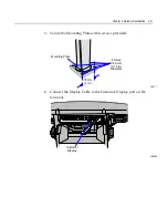
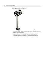
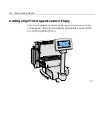
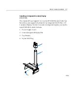
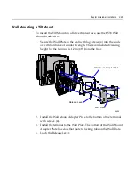
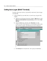
Installation Procedure
1.
Route
the
cable
(display
connector
end)
up
through
the
Power
Supply
Cover,
Display
Post,
and
Top
Bracket.
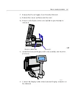
This
is
a
tight
fit
and
the
connector
has
to
be
angled
in
order
to
make
it
though
the
openings.
Use
care
to
not
damage
the
wires.
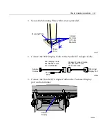
19949a
Top Bracket
Display Post
Power Supply Cover
4 x 20 Integrated
High-Post Cable
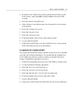
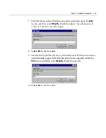
2.
Insert
the
post
into
the
hole
on
the
top
of
the
Power
Supply
Cover.
Note
the
orientation
above.
The
slot
on
the
bottom
end
of
the
post
should
face
the
inside
of
the
cover.
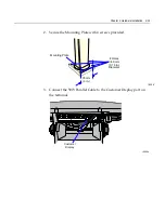
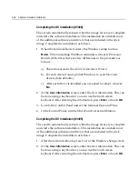
3.
Install
the
Top
Bracket
onto
the
post.
Summary of Contents for 7454
Page 1: ...NCR 7454 Retail Terminal Release 2 2 Hardware User s Guide 18004 NCR B005 0000 1256 Issue H...
Page 38: ...1 26 Chapter 1 Product Overview 16 High Post Mount 17198...
Page 50: ......
Page 100: ...3 10 Chapter 3 Setup...
Page 138: ...4 28 Chapter 4 Operating System Recovery...
Page 148: ...5 10 Chapter 5 BIOS Updating Procedures...
Page 151: ...Chapter 6 NCR 7454 4x20 Customer Display 6 3 Character Set Page 1 International...
Page 152: ...6 4 Chapter 6 NCR 7454 4x20 Customer Display Page 2 Japanese...
Page 153: ...Chapter 6 NCR 7454 4x20 Customer Display 6 5 Page 3 Code Page 850...
Page 166: ...6 18 Chapter 6 NCR 7454 4x20 Customer Display...
Page 178: ......
Page 179: ......
Page 180: ...B005 0000 1256 Dec 2002 Printed on recycled paper...


