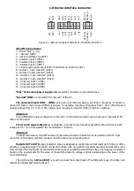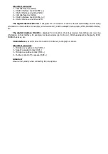
telematics server (separate packet with this information).
Digital temperature sensor codes, keys, maps and keyfobs of the identification systems can be read in the
NTC Configurator program in the “Telemetry” window with external power connected to the device.
2.9 Amplifier connection for voice information
The devices have the "Autoinformer" function designed to automatically inform passengers about stops.
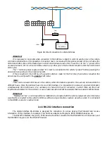
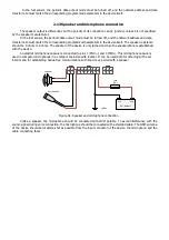
To implement voice information, an external audio signal power amplifier must be connected to the device.
The amplifier should be selected based on the number and power of the speakers or acoustic systems
connected to it. The power and the number of speakers are determined depending on the type of vehicle on which
the automatic information system is installed. Also, when choosing an amplifier, you should take into account the
range of permissible supply voltage, which must correspond to the voltage of the vehicle's on-board network.
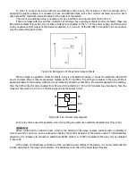
The linear amplifier input should be connected to the linear audio signal output L
OUT
(pin 7 of the main device
connector). The nominal input voltage of the audio signal at the device L
OUT
output is ~ 500 mV. If the amplifier has
2 channels, then to increase the power, you can connect both amplifier channels in parallel to one output.
To avoid interference with audio signal when informing, the connection should be made with a shielded cable.
The GSM antenna of the device should be located as far as possible from the input connector of the device, amplifier,
speaker and from the wires connecting them.
Fuse
(1А)
«GND»
«+»
«-»
Car battery
4
2
3
1
14
7
13
6
12
5
11
4
10
3
9
8
2
1
6
5
4
3
2
1
+
-
Speaker
+
-
Speaker
R
L
OUT
R
L
IN
+
-
Power
Low frequency
amplifier
«GND»
Shilded
cable
Fuse
Figure 46. Amplifier connection for voice information
2.10 CAN interface connection
The device has its own CAN interface, which allows to connect to the vehicle CAN bus directly without additional
adapters or decoders.
CAN bus is being connected using pins 1 and 4 of Microfit-6 connector. The CAN bus contact “CANL” is being
connected to pin 4 of the connector, and the “CANH” bus to pin 4.
The connection location to the car CAN bus depends on vehicle’s model and a year of its manufacture.
In some cars, all the necessary data from CAN bus can be obtained by connecting to the OBD-II diagnostic
connector.
Summary of Contents for SIGNAL S-2651
Page 16: ...Figure 19 Figure 20...

