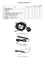
2.3 GSM- and GLONASS/GPS antennas connection
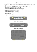
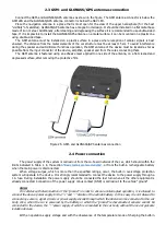
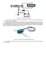
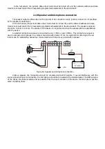
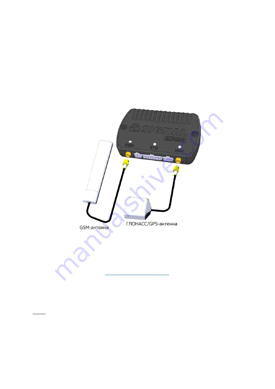
Connect the GSM- and GLONASS/GPS antennas as shown in the figure. The GSM antenna connector is below the
GSM LED and the GLONASS/GPS antenna connector is below the NAV LED.
Place the navigation antenna in a place that is most open for the view of the upper hemisphere (for the best
"visibility" of satellites). GLONASS/GPS antenna has a magnet in its design. It should be installed on a flat metal base
made of iron or steel. Additionally, after cleaning and degreasing the surface it is recommended to use double-sided
tape. If it is impossible to install the GLONASS/GPS antenna on a metal surface, it can be mounted on a plastic one
using double-sided tape.
The GSM antenna must be installed on a plastic surface in a place where reception of cellular signals is best
ensured. The distance from the metal elements of the car structure must be at least 15 sm. To avoid interference
during the speaker and autoinformer functions operation, the GSM antenna of the device must be located as far as
possible from the input connector of the device, amplifier, speaker and from the wires connecting them.
The GSM antenna is fastened using an adhesive layer applied to one side of the antenna, on a flat cleaned and
degreased surface, after removing the protective film.
Figure 25. GSM- and GLONASS/GPS antennas connection
2.4 Power connection
The power supply of the system is carried out from the on-board network of the car, which should within the
limits indicated in Table 1, in the section
"Basic technical characteristics"
, or from the built-in rechargeable battery
when the main power is disconnected.
When voltage surges, which is more than the specified ratings, occur, the built-in overvoltage protection
system will operate in the device. It is strongly recommended to connect the device to the power supply through a
1 A fuse. During installation the power supply should be connected the last turn when all the other equipment is
already connected. Connection of the power supply minus contact (GND) is carried out to the vehicle “ground”.
Note:
On vehicles with disconnection of the “ground” in order to ensure uninterrupted operation, it is allowed to
connect the device power supply to the “+” and “-” circuits of the vehicle battery. In this case, it is not allowed to
connect any sensors, signal circuits or power supply circuits through which the device can be connected to the car
body. Also, when the car is powered by the battery in which the “ground” is disconnected, sensors cannot be
connected to the device, the “-” power supply of which is connected to the car body, without the use of galvanic
isolation devices.
With an operation supply voltage and with the observance of the temperature mode of charging the built-in
Summary of Contents for SIGNAL S-2651
Page 16: ...Figure 19 Figure 20...

