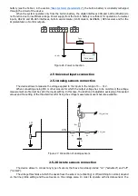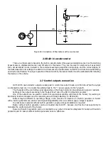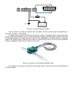
In order to connect car sirens without an additional control input, the inclusion of which is carried out by
applying the supply voltage, it is necessary to use an additional relay, since the current consumed by such a siren
may exceed the maximum allowable value for the output of the device.
The use of an additional relay is necessary for any load that can consume more than 500 mA.
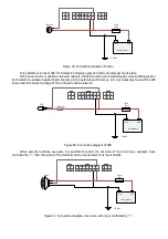
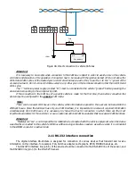
There are relays with four and five contacts, but all relays have winding contacts (control contacts), these are
85 and 86 contacts (Figure 38). One of these contacts is connected to the “+” of the power supply, and the second
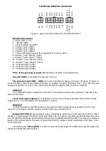
to any negative control output of the device (contacts 8, 9, 10 and 11 of the Microfit-14 connector). All connections
must be made through the fuse.
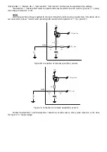
Figure 38. Designation of the external relay contacts
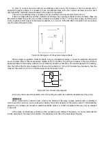
When voltage is applied to control contacts, relay is activated and closes or opens the electrical circuit with
power contacts. Power contacts are always marked as 30, 87 and 87a. The 30th pin is always in the relay. Without
applying voltage to the winding contacts, it is permanently closed to contact 87a. If a signal is applied to the winding,
then the 30th contact is disconnected from 87a and connected to 87. 87a or 87 contacts may be absent, then the
relay will only work to turn on or off (closing-opening) the power circuit.
30
85
86
87a
87
Figure 39. Five-contact relay diagram
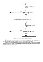
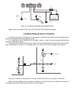
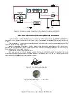
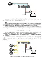
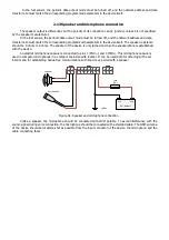
Such relay can be used for example, when connecting an automotive electromechanical lock (Figure 40).
Attention!
When controlling the inductive load, which is the winding of the relay, reverse currents with a potential of
more than 200 V can occur. Such a voltage can destroy the control transistor of the device output. To limit backflow
emissions, it is necessary to connect an additional 1N4007 diode (1A, 1000V) in parallel to the relay coil, as indicated
in figure 40
At the stage of correctness verification of the connection and settings of the device, it is not recommended to
include actuators in the relay circuit directly. It is advisable to do this at the final stage of testing.
Summary of Contents for SIGNAL S-2651
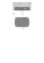
Page 16: ...Figure 19 Figure 20...

