background image

8120 

 Installation and Operation Manual

54

Displaying a boat on the chart

1  Press   or   to select a boat. 
2  Press 

MENU

 and select 

Display

. The 

Instrument switches to chart window, with 
the selected boat position in the middle 
(see Boat positions above).

Going to a boat

1  Press   or   to select a boat. 
2  Press 

MENU

 and select 

Goto

. The 

Instrument starts navigating to the boat’s 
position (see Boat positions above).

Creating a waypoint

Polled and buddy track boats are not 
waypoints. To create a waypoint at the position 
of a polled boat (see Boat positions above):
1  Press   or   to select a boat. 
2  Press 

MENU

 and select 

Create 

waypoint

. Edit the waypoint data if 

required (see section 5-2-7).

Editing a waypoint

A distress message creates a waypoint for the 
boat or you can create a waypoint at a polled 
boat’s position. To change the data of these 
waypoints:
1  Press   or   to select a boat. 
2  Press 

MENU

 and select 

Edit waypoint

Edit the waypoint data if required (see 
section 5-2-7).

Deleting a boat

At the Distress or Poll windows:
1  Press   or   to select a boat. 
2  Press 

MENU

 and select 

Delete

. The boat 

is deleted from that window. Delete any 
boat waypoint manually (see section 
5-2-5).

Buddy track boats automatically disappear 
from the Buddy track window when your DSC 
radio can not pick up their signal.

Deleting all boats

At the Distress or Poll windows:
1  Press   or   to select a boat. 
2  Press 

MENU

 and select 

Delete all

. All 

boats are deleted from that window and 
any boat waypoints are deleted.

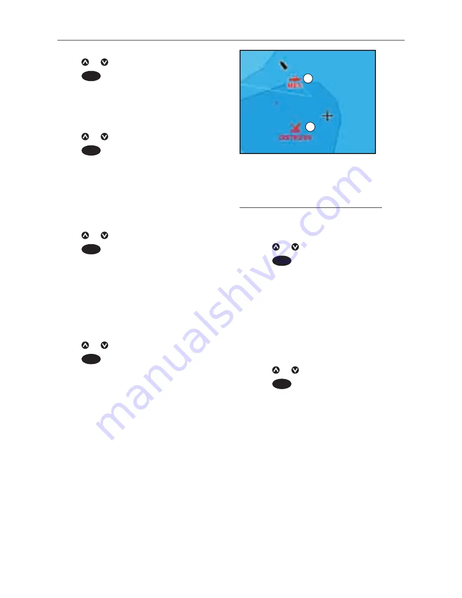
16-2 Using the windows

On a chart window:
A  Distress boats are distress waypoints
B  Buddy track boats are buddy symbols

A

B

Summary of Contents for Datahelm 8120

Page 1: ...w w w n a v m a n c o m Datahelm 8120 Installation and Operation Manual...

Page 2: ...3 Distance and bearing calculator 22 3 4 Projected course 23 3 5 Tracks and tracking 23 4Videowindow 24 5Navigation Highwaywindow 25 6Navigation Waypoints 25 6 1 Waypoints window 26 6 2 Managing wayp...

Page 3: ...s 65 17 8 Setup Alarms 65 17 9 Setup Units 66 17 10 Setup Comms 67 17 11 Setup Calibrate 67 17 12 Setup Time 69 17 13 Setup Favourites 69 17 14 Setup Simulate 69 18Installation 70 18 1 Installation Wh...

Page 4: ...ernment charts Only official government charts supplemented by notices to mariners contain the information required for safe and prudent navigation Always supplement the electronic information provide...

Page 5: ...ver status 7 Saving and loading data with a user card 15 User card Chart data Chart features built in world chart 3 2 Chart details 3 2 4 5 Chart card Tides at a port 14 Chart card Alarms Built in ala...

Page 6: ...ed highly integrated marine chartplotter and fishfinder It is easy to use and has a very large easy to read and use colour display Complex functions can be performed with only a few key presses taking...

Page 7: ...tion data to be transferred to another compatible instrument see section 14 Removing a plug in card Turn the 8120 o see section 2 2 Open the card cover on the right of the display Inserting a plug in...

Page 8: ...ch locking collar anticlockwise until you can pull the plug out 4 Store the 8120 in a dry clean place Replacing the display unit 1 Plug the connectors into the back of the display unit Match the conne...

Page 9: ...ects which window you are working with The Active window is indicated with a red border The key allows you to quickly switch between your saved favorite displays GOTO AUTO For a navigation display Sta...

Page 10: ...highlight to the command for example Goto cursor then press ENTER Changing data First press or to move the highlight to the data to change then a To change a tick box means On or Yes means Off or No...

Page 11: ...urn the Instrument off manually 2 3 Backlight and night mode To go to the Backlight window press briefly Backlight The display and keys are backlit To change the backlight level select Backlight then...

Page 12: ...rate Press ESC to clear the alarm The alarm will sound again if the alarm condition occurs again The Instrument has user settable alarms see section 17 8 CAUTION CAUTION DANGER WARNING MOB will not wo...

Page 13: ...ull size press DISPLAY and select the window 2 7 The main windows Note 1 The windows available depend on the optional sensors and instruments that are installed see section 1 1 2 Set up commonly used...

Page 14: ...20 Installation and Operation Manual 14 To show one of the other windows full screen press DISPLAY select More and select the window Press ESC to return from one of these windows to the previous windo...

Page 15: ...Press DISPLAY and select Delete window Exchanging two windows on the display 1 Press until the first window has a red border 2 Press DISPLAY select Replaceand select the second window The 8120 exchang...

Page 16: ...favourite display to the list 1 Set up the display with the window or windows you want in the new favourite see sections 2 7 1 and 2 7 4 2 Press DISPLAY and select Save this display The 8120 displays...

Page 17: ...When the boat is navigating to a point the compass also shows bearing to the destination BRG a red symbol In this example BRG is 205 M and COG is 321 M To turn the compass off or on 1 Press MENU and s...

Page 18: ...autopilot the Instrument will send data to the autopilot to steer the boat to the destination Start the autopilot before starting to navigate to the point If the Instrument has no autopilot steer the...

Page 19: ...ute from the routes window 1 Go to the routes window 2 Then follow step 3 as in starting a route from the chart window above Navigating The Instrument navigates to each waypoint on the route in turn a...

Page 20: ...Land I Sea J The cursor see section 3 2 1 K A typical waypoint see section 5 Note To change the types of information displayed on the chart see section 17 2 To change to a perspective view of the cha...

Page 21: ...ngitude has a boat symbol to show this 36 29 637 N or S Latitude 175 09 165 E or W Longitude If the cursor has been moved in the last ten seconds then the position is the cursor s position and the lat...

Page 22: ...e to or 3 3 Distance and bearing calculator The distance and bearing calculator can plot a course of one or several legs and show the bearing and length of each leg as well as the total distance along...

Page 23: ...ly along the reference track back into the harbour Record reference tracks in good conditions 3 5 Tracks and tracking When recording is on and the track becomes full then recording continues and the o...

Page 24: ...DISPLAY and select Video Adjusting the video picture colour 1 Press MENU 2 Press or to highlight a control then press or to adjust the control 3 To return the colours to their default settings select...

Page 25: ...nger waypoint the unit can sound an alarm see section 17 8 A display option Controls how the waypoint is displayed on the chart see section 17 2 5 Navigation Highway window The highway window has a bi...

Page 26: ...lect Create 2 A new waypoint with a default name and data is created at the boat position 3 Change the waypoint data if necessary see section 5 2 7 Note Waypoints can also be created when a route is c...

Page 27: ...nt data when it is displayed in a window 1 Select the data to change Press ENTER Use the cursor keys to change the data Press ENTER 2 If necessary repeat the above step to change other data 3 Select S...

Page 28: ...e new waypoint data see section 5 2 7 You can not use a Danger waypoint in a route 1 In the chart window press MENU and select New route 2 The route is given a default name i Change the name if necess...

Page 29: ...o end creating the route i Press MENU and select End 7 To delete the route i Press MENU and select Delete ii Select yes to confirm Tip The distance and bearing calculator can also be used to enter a c...

Page 30: ...list of the waypoints 3 Edit the route as described in section 6 2 1 B starting at step 3 7 2 3 Displaying a route on the chart To view the selected route at the centre of the window 1 In the routes w...

Page 31: ...d by the Instrument s standard GPS antenna The accuracy of the corrected GPS position is typically better than 5 m 15 ft for 95 of the time WAAS covers all of the USA and most of Canada EGNOS will cov...

Page 32: ...s section explains how to interpret the sonar displays when and why to use the different frequencies and how fish are detected and displayed It also describes Gain and Range and shows examples of some...

Page 33: ...e history moves across the window more slowly because the echoes take longer to travel between the bottom and the boat For example when the scroll speed is set to Fast at depths over 1000 ft 300 m it...

Page 34: ...h of echoes The colours indicate differences in the strength of the echo The strength varies with several factors such as the Size of the fish school of fish or other object Depth of the fish or objec...

Page 35: ...r than the 200 kHz cone and penetrates to a greater depth with minimal loss of the return signal However it produces a lower definition display with more shadow compared to the 200 kHz frequency This...

Page 36: ...centre of the sonar cone When to use 50 200 kHz Operating the Instrument at both 50 kHz and 200 kHz simultaneously on a split window can be very useful when operating in shallow to medium water typic...

Page 37: ...Installation and Operation Manual 37 50 kHz display 200 kHz display 200 50 Khz display Mixed display 1 minute ago 30 seconds ago Now Comparison of the same fish scenario displayed at different frequen...

Page 38: ...17 3 Fish filter To see the maximum amount of information from the echoes turn Fish symbols off Fish appear as arches on the window Fish arches In good conditions a fish passing through the cone shap...

Page 39: ...h is below the range the bottom will not appear on the window Manual range is useful if the bottom depth changes rapidly because Auto range will cause the window to change range frequently To set Manu...

Page 40: ...en return echoes less than 50 of the maximum signal are ignored There is a separate threshold setting for each sonar frequency 50 kHz and 200 kHz The gain window To display or change the current setti...

Page 41: ...ion 2 7 3 B Optional compass see section 2 7 4 C Depth D Colour bar E Bottom F Range G Fish symbols with depth H Depth line The window scrolls from right most recent echoes to left oldest echoes If th...

Page 42: ...ified in the zoom section Press or to adjust the zoom range the range of depths included in the zoom section If Bottom lock is on the zoom depth the depth of the zoom section is adjusted automatically...

Page 43: ...o the bottom The zoom bar on the far right shows the area of the history that is magnified in the zoom section Use the or keys to adjust the zoom range The Instrument calculates the zoom depth automat...

Page 44: ...Note Setting the gain higher will display more detail from weak echoes like fish but will loose detail from the strong echo from the bottom Fish recognition The echo strengths shown on the A scope ca...

Page 45: ...lect the layout to change see above 2 Press MENU and select Gauge setup 3 Highlight the gauge to change Press ENTER and select the data to display in the gauge 4 Repeat the above step to change other...

Page 46: ...y fill the tank and follow procedure A about every tenth time you add fuel B When you part fill the tank 1 Before adding fuel go to the fuel window and write down the value of Remaining which is the a...

Page 47: ...th engines are under the same load Speed If the Instrument has both GPS and paddlewheel speed available then you can select which to use The choice affects the calculated Range and Economy see section...

Page 48: ...curve then select New 4 Enter the comfortable maximum RPM you have measured for the engine Do not use the maker s maximum RPM 5 The Instrument then asks you to set the minimum RPM Set the throttle for...

Page 49: ...ER select Other then select Fuel 2 Press MENU press ENTER and select the name of the curve to display on the fuel window Using a curve Compare your boat s performance now at the current RPMs with the...

Page 50: ...Current time and chosen date for display C Tide chart D Night E Dawn F Day G Dusk H Tide height I Time cursor a vertical dotted line Press or to move cursor sideways J Time of cursor and tide height...

Page 51: ...t If a new route has the same name as an existing route but has different data then the Instrument asks which route to keep A track file The new track will replace the existing track in the Instrument...

Page 52: ...ed Any data files on the card are deleted 1 Press MENU and select Card 2 Select Format 3 Select Yes to confirm 16 DSC Buddy track windows Buddy track requires an optional Navman DSC VHF radio to be in...

Page 53: ...at the boat position Distress waypoints have default names like DSTRSS01 The Instrument displays a Distress warning Select OK to return to what you were doing Display to switch to Chart and display th...

Page 54: ...istress message creates a waypoint for the boat or you can create a waypoint at a polled boat s position To change the data of these waypoints 1 Press or to select a boat 2 Press MENU and select Edit...

Page 55: ...ion of the unit using the default settings before making any changes in these menus To go to a setup option menu press SETUP to display the setup menu then select an option Note 1 The Setup menu optio...

Page 56: ...17 4 Sonar see 17 3 Track see 17 6 Fuel see 17 5 Chart see 17 2 General Water Land and Other submenus 17 2 Logs see 17 7 Comms see 17 10 Units see 17 9 Alarms see 17 8 Time see 17 12 Favourites see 17...

Page 57: ...key presses Auto power off See section 2 2 Factory reset This option returns all of the Instrument settings except the language waypoints and routes to the default factory settings shown on the setup...

Page 58: ...ision Map datum Instrument GPS positions are based on a worldwide reference datum known as WGS 84 Most paper charts are based on WGS 84 However some paper charts are based on other datums In these cas...

Page 59: ...cation Clearing the map shift Clearing the map shift removes any map shift from the cartographic features on the Instrument chart window 1 In the Chart setup menu select Map shift 2 Press MENU and sel...

Page 60: ...ext icon size Select the size of chart text and icons Water submenu Water features displays nature of seabed for example M shows areas of mud and tide station icons Bathymetric s lines Displays underw...

Page 61: ...he minimum strength fish echo that will be displayed as a fish symbol Higher values will display more fish symbols Digit size Use this to remove or change the size of the depth window on the sonar win...

Page 62: ...easurements and averaging them A lower value averages measurements over a shorter period of time This gives the most accurate value but has the most fluctuations A higher value averages measurements o...

Page 63: ...ucer s 3 Run the engine at normal cruising speed until at least 4 gallons 15 litres of fuel has been used per engine 4 Check the actual amount of fuel used per engine by refilling the portable tank s...

Page 64: ...lect a track number The Instrument starts recording the boat s course into the selected track Display Off No track is shown on the chart 1 to 5 select a track number The selected track is shown on the...

Page 65: ...als 17 8 Setup Alarms For the XTE Fish and Loss of DGPS fix alarms select to turn the alarm on or select to turn the alarm off For the other alarms enter a trigger value to turn the alarm on The alarm...

Page 66: ...ue Fish 1 short echo matches the pro le of a sh beep Temperature 1 2 sec temperature equals the alarm trigger value Temperature 1 2 sec rate of change of temperature equals the alarm rate trigger valu...

Page 67: ...itude and longitude transmitted in NMEA sentences NavBus NavBus is the preferred method for connecting the Instrument to other NAVMAN instruments Select this if the instruments are connected using Nav...

Page 68: ...ahrenheit or C Celsius see section 17 9 Temperature filter Water turbulence and currents cause the water temperature to fluctuate slightly To give stable readings the Instrument calculates these value...

Page 69: ...late The options required for Normal are Speed The simulated boat speed to use Course The simulated course over ground Note To select the start point go to the chart window before starting the simulat...

Page 70: ...ching or retrieving of the boat To help ensure proper operation do not mount any part or cable within 0 5 m 20 of the plane of a radar antenna or within 1 m 3 ft of a compass or source of electrical n...

Page 71: ...ot in use Front Bezel Note Fit this after installing the display unit Power cable Mounting bracket and locking knobs Bracket mounting screws 5 x14 Gauge self tapping screws Flush mounting screws 4 x 8...

Page 72: ...HF radio Tracks other boats with GPS receivers and DSC radios and displays barometric pressure see section 18 9 SmartCraft With one or two SmartCraft capable Mercury petrol gasoline engines the Instru...

Page 73: ...cket mounting chose a flat area where the display will not be subjected excessive vibration Select an area with adequate clearance for cabling and access to the power source Before drilling any holes...

Page 74: ...mounting template 6 Connect all cables to the rear of the unit before placing the unit into the console 7 Firmly secure the unit in place with the 4 x 8 gauge self tapping screws Note the 5 x 14G self...

Page 75: ...onnector Power data cable Yellow Red Black Ignition Ignition switch Main switch 12 24 V DC Fuses 2A Power data cable Red Yellow Black 18 4 Installation Power data cable Main switch 12 24 V DC Fuse 2A...

Page 76: ...VMAN dealer DGPS Source Enables or disablesthe satellite based DGPS correction see section 7 The options are None or WAAS EGNOS Do not Enable WAAS EGNOS outside their coverage areas or the accuracy of...

Page 77: ...its Wire the Instrument for auto power see section 18 4 During setup a set the fuel data see section 17 5 18 8 Installation Navman diesel sensors Fit the optional diesel fuel kit following the instruc...

Page 78: ...Craft engines with an optional SmartCraft gateway The display unit can display engine data and trim and can control troll speed Note Fit a single gateway for single engines and a dual gateway for dual...

Page 79: ...larm NavBus and the Instrument The Instrument can Display wind speed and direction from an optional Navman Wind instrument Receive and display depth from an optional Navman depth instrument Receive an...

Page 80: ...ll connectors are plugged in and the display unit is in place 2 If the display unit is bracket mounted adjust tilt and rotation for best viewing and hand tighten the knob 3 Insert any required C MAP c...

Page 81: ...l sonar transducer required Depth range 1m 3 ft to 1000 m 3300 ft Sonar output Power Variable up to 600 1000 W RMS Dual frequency 50 khz and 200 kHz Depth acquisition time from startup Typically 2 sec...

Page 82: ...74 Ireland 1965 ISTS 061 Astro 1968 ISTS 073 Astro 1969 Johnston Island 1961 Kandawala Kerguelen Island 1949 Kertau 1948 Kusaie Astro 1951 L C 5 Astro 1961 Leigon Liberia 1964 Luzon M Poraloko Mahe 19...

Page 83: ...ctions in this manual It is possible in many cases to solve difficulties without having to send the display unit back to the manufacturer for repair Please follow this troubleshooting section before c...

Page 84: ...ate mode Turn simulate mode off see section 17 14 c Local time offset is wrong see section 17 12 The Local Time Offset must be changed when daylight saving time starts or ends 2 6 Autopilot not respon...

Page 85: ...The boat must be travelling through the water to generate an Economy reading b Check that the paddlewheel on the transducer is spinning freely and that the two magnets in the paddlewheel are still in...

Page 86: ...llower water 4 3 The bottom is displayed too far up the screen The Instrument may have Manual Range selected and the selected Range value is too high for the depth Either change the Instrument to Auto...

Page 87: ...aft Goto A simple way of navigating straight to a waypoint or to the cursor position see section 3 1 GPS Global Positioning System A satellite based navigation tool see section 7 Leg The straight segm...

Page 88: ...8 an alarm will sound if the boat reaches a CDI line COG Course Over Ground Direction in which the boat is moving over the ground CTS Course To Steer Optimum course to steer to return to the plotted...

Page 89: ...ce to radio or television reception which can be determined by turning the equipment o and on the user is encouraged to try to correct the interference by one or more of the following measures Reorien...

Page 90: ...Lon 174 44 535 E Lat 36 48 404 S Made in New Zealand MN000444A Datahelm 8120 Installation and Operation Manual...

Reviews: