background image

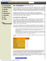
                    Multi-Image Show Set-up & Operation

Turning  the

Power  On

Determining

Projected

Image  Position

Turn the source select switch to “2.”  Connect the power
cord 1 to source-1  and to the wall outlet.  Connect power
cord 2 to source-2 and to the “out” connector of the
dissolve controller.  Use the same power supply for
source-2 as that of dissolve controller.

Now, connect the dissolve cord from the dissolve control-
ler to either controller in-1 for an AVL or Kodak controller,
or to controller in-2 for a Dataton controller.

Next, turn the power switch to ON (dissolve shutter is
initialized) and the lamp switch to ON.  The LED will light.

Advance the slide tray by pressing the forward/reverse
switch.  In the case of a 3-projector multi-image show
using a set-up slide in each projector (e.g. AMI), turn ON
the set-up switch of projector “B.” This will be the basis for
positioning the image.  Open the dissolve shutter and
adjust the position of the image  vertically and horizontally
by means of  shift-1, shift-2 and the leveling feet.

After the image size has been determined, adjust the
image focus.  Keep showing basic projector “B” and turn
the set-up switch of projector “A” ON.  Adjust projector “A”
in the same manner as stated above and turn its set-up
switch to OFF.  Overlap picture “A” on picture “B.”  Then
adjust projectors “B” and “C” in the same manner.

Finally turn the set-up switch of projectors “A”, “B” and “C”
to ON to show the slide images of all three projectors and
confirm how they are overlapped.

After the overlapping has been confirmed, turn the set-up
switches of projectors “A”, “B”, and ”C” to OFF.  Then
return the slide tray to the “starting point.”

To start projection, turn the AVL/Dataton dissolve controller
ON.  The slide projectors will operate according to the
signals from the dissolve controller.

When projection is finished, turn OFF the lamp switch.
Allow the lamp to cool for 2-3 minutes before turning the
power switch OFF.

Starting  &

Finishing

Projection

18

Summary of Contents for ColorPro

Page 1: ...COLORPRO Mini Xenon Slide Projector Instruction Manual The World Leader in Image Quality...

Page 2: ...ifications 5 Projector Features 8 System Diagrams 12 Lamp Installation 14 Setting Up the Slide Tray 15 Installing Removing the Slide Tray 16 Standard Set up Operation 17 Projector Functions 18 Multi I...

Page 3: ...ntional halogen lamp slide projectors that colorize your slide images with a yellowish cast the ColorPro projector presents your slides exactly as photographed Colors are vibrant Whites are bright whi...

Page 4: ...wer Connector n Instruction Manual Your new Navitar ColorPro Xenon slide projector is constructed of the finest electronic components available and designed for maximum reliability For servicing conta...

Page 5: ...u l l I x u L 0 0 8 1 e z i S t n u o M s e d i l s 2 x 2 e z i S e r u t r e p A s e d i l s r e p u s m m 5 3 x 5 3 r o m m 5 3 x 3 2 s n e L n o i t c e j o r P n o i t c e j o r p e d i l s d r a...

Page 6: ...a multi image system When the slide tray is in the zero position the contact is open It is closed in any other position Remote 1 Connector Connects the remote control for remote forward reverse and f...

Page 7: ...of the projected image It can be moved 6 of picture size without distortion CP 300SD only Projection lenses A wide variety of Navitar slide projection lenses are available for use with your ColorPro...

Page 8: ...erval timer switch The slide tray will automatically wait the selected time before advancing to the next slide Fade Select Switch Fade timer switch for fade in out projection Auto Focus Switch The on...

Page 9: ...System Diagrams 8 300AF Top View 300AF Front View FOCUS IN OUT TRAY LOCKING LEVER SHIFT KNOB SLIDE GATE SLIDE TRAY FORWARD REVERSE LAMP ON OFF PROJECTION LAMP SLIDE TRAY FRONT ADJUSTABLE LEGS...

Page 10: ...iagrams 9 300AF Side View 300AF Rear View or REMOTE 2 CONNECTOR LAMP ON OFF AF ON OFF POWER ON OFF SIDE COVER POWER SUPPLY CONNECTOR REMOTE 1 CONNECTOR FORWARD REVERSE FOCUS IN OUT CONNECTOR FOR RANDO...

Page 11: ...SD Top View 300SD Front View TRAY LOCKING LEVER SLIDE GATE SLIDE TRAY TIMER SWITCH FADE SELECT SWITCH AUTO FOCUS ON OFF LAMP HOUSE VERTICAL SHIFT 1 PROJECTION LENS HORIZONTAL SHIFT 2 SLIDE TRAY FRONT...

Page 12: ...00SD Side View CONNECTOR FOR RANDOM ACCESS CONTROLLER IN 2 CONTROLLER IN 1 REMOTE 2 REMOTE 1 ZERO CONNECTOR POWER ON OFF LAMP SET UP ZERO POINT INDICATOR FOCUS REVERSE FORWARD FADE ON OFF SIDE COVER S...

Page 13: ...oils from hands may damage the quartz envelope Always allow the bulb to cool before handling When necessary clean the bulb with ordinary rubbing alcohol only when bulb is cool Place the bulb on soft...

Page 14: ...e positive lead screw on the side of the lamp Unscrew the black end cap and remove the bulb by holding the metal tip Hold the bulb by the metal end and place it into the reflector Make sure that the p...

Page 15: ...d 3 Turn each slide up side down 4 Using a felt pen write a slide number on the right upper corner of each slide 5 Put each slide in the slide compartment in such a way that the number is seen at the...

Page 16: ...ned with a latch Unfasten the latch and try to install the slide tray again To remove the slide tray follow the above procedure matching the slide tray zero position with the slide gate If you push th...

Page 17: ...of the projector and fasten with a screw For adjusting the projected image size move the position of the projector forward or backward or use a zoom lens To change the height and slant of the image p...

Page 18: ...p then simultaneously press the forward and reverse buttons to memorize the tray position as empty Each position memorized as empty will be skipped as the tray advances Releasing Memory Memories are a...

Page 19: ...ge Open the dissolve shutter and adjust the position of the image vertically and horizontally by means of shift 1 shift 2 and the leveling feet After the image size has been determined adjust the imag...

Page 20: ...ontrollers The remote 1 connector is used for the Kodak Ektagraphic III remote controller 1 Focus Adjustment 2 Slide Forward 3 Slide Reverse 5 COM The remote 2 connector is used to turn the lamp on an...

Page 21: ...dification by someone other than Navitar Further this warranty does not cover any routine maintenance work that is reasonably expected to be performed by the purchaser No responsibility is assumed for...

Page 22: ...NAVITAR Inc 200 Commerce Drive Rochester NY 14623 USA 716 359 4000 phone 716 359 4999 fax http navitar com internet info navitar com email...

Reviews: