background image

BHM 

11/18/14 

NTV-DOC117  


Agreement

End user agrees to use this product in compliance with all State and Federal laws. NAV-TV Corp. would not be held liable for 

misuse of its product.  If you do not agree, please discontinue use immediately and return product to place of purchase. This product is 
intended for off-road use and passenger entertainment only.  

4 | 

P a g e


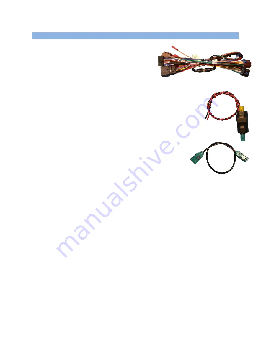
Barracuda Installation 


1.


After the radio has been removed, locate the 
factory 

brown and black plugs

 that match those 

found on the provided 

Plug & Play T-Harness


and connect them securely to the female side.  
 

2.


On the provided 

GPS Antenna Relay

, splice the 

black wire

 to a ground (-) source and 

connect the 

red wire 

to 

OUTPUT A

 (white/blue wire) from the 

Barracuda module’s harness. This wire will be labeled.  

Note: Be sure to program ‘OUTPUT A’ to ‘Antenna Interrupt’ so that the GPS 
antenna signal is separated when VIM is active. (See Programming)


3.


Locate the factory GPS antenna cable (usually blue) and connect it to the 

turquoise 

connector

 on the provided 

GPS Antenna Relay

.   


4.


Connect the provided 

GPS Antenna Extension

 to the 

yellow 

connector

 of the 

GPS


Antenna Relay

, and the free end back to 

the radio. 
 

5.


If not adding any additional cameras, keep both the 

black RCA’s


connected together, 

otherwise you will 

lose the factory rear camera image


6.


If forced factory rear camera (viewing camera image at any time) is desired:


a.


Locate the factory 

rear camera module 

(usually under pass seat or rear section 

of vehicle)


or 

BCM 

(usually mounted near the drivers firewall) 

b.


Locate the 

blue reverse 12v wire

 which runs to the camera module, 

cut it in half


c.


Extend the 

Blue wire (PIN 12) 

from the Barracuda’s main harness to the camera 

module/BCM 

d.


Connect the Barracuda’s 

Blue wire

 to the 

camera module side 

of the cut wire 

e.


Insulate the other end of the cut wire to prevent a short! 


7.


If adding an additional front camera, 

the RCA’s must be connected differently than 

step 5


(See the diagrams on page 5 for visual aid). Power for the front camera can be 

connected to 

OUTPUT B

 (white/orange wire). 

Be certain to program OUTPUT B for


‘Front Camera’

 if using white/orange wire. 


8.


Connect the Barracuda module to the 18-pin plug located on the 

Plug & Play T-Harness

.  

9.


Proceed to 

Barracuda Programming

 (page 6). 

Summary of Contents for Barracuda

Page 1: ...Barracuda Video in Motion for select 07 11 GM vehicles NTV KIT211 BHM 11 18 14 NTV DOC117 3950 NW 120th Ave Coral Springs FL 33065 TEL 561 955 9770 FAX 561 955 9760...

Page 2: ...11 GM vehicles with the 29 BIT GM LAN radios Kit Contents Barracuda pin out PIN Description Color 1 12v Constant Red 2 NOT USED White 3 NOT USED Pink 4 NOT USED Orange 5 RX FLIR Control Brown 6 RCA Si...

Page 3: ...m panel on the passenger side just over the glove compartment This will allow removal of radio trim 2 Gently pry up on center console trim and disconnect cigarette lighter plug 3 Remove the trim panel...

Page 4: ...Relay 4 Connect the provided GPS Antenna Extension to the yellow connector of the GPS Antenna Relay and the free end back to the radio 5 If not adding any additional cameras keep both the black RCA s...

Page 5: ...ance with all State and Federal laws NAV TV Corp would not be held liable for misuse of its product If you do not agree please discontinue use immediately and return product to place of purchase This...

Page 6: ...w mirror button for 2 seconds The following instructions will appear on the instrument cluster display a Use the remote mirror Down key to cycle through the features VIM CIM etc b Use the remote mirro...

Page 7: ...hen Control in Motion is turned on VIM is not enabled 2 VIM DEFAULT Stores the default setting for Video In Motion ON VIM is Always ON until the user turns it off OFF VIM is Always OFF until the user...

Page 8: ...p Arrow is held for 2 seconds Press and Hold UP Arrow for 2 seconds turns on off 12V output from port A or B Pulse if Up Arrow is held for 2 seconds Press and Hold Up Arrow for 2 seconds enables a 12V...

Page 9: ...s Always OFF Zoom is normally disabled Always ON Zoom is always on On High Beam Zoom on when high beams are active On High Beam or 20MPH Zoom is enabled on High Beam or when the speed is greater than...

Page 10: ...t arrow will enable disable Control in motion Control in Motion allows the user to access radio functions that are normally blocked while the vehicle is moving Note When activated Control in Motion CI...

Page 11: ...nce with all State and Federal laws NAV TV Corp would not be held liable for misuse of its product If you do not agree please discontinue use immediately and return product to place of purchase This p...

Reviews: