background image

5

&KHFNLQJWKH'ULYH%HOW7HQVLRQ

To test the Drive Belt tension, sit on the bike and use the pedals at approximately 20 RPM. Then accelerate quickly 
(speed burst) to your maximum ability and feel whether the Drive Belt slips. If the pedals move normally with no skipping 
(slip), the tension is correct. If the Drive Belt slips, refer to the “Adjust the Belt Tension” procedure in this manual.

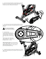
/HYHOLQJWKH0DFKLQH

The machine needs to be leveled if your workout 
area is uneven. Levelers are found on each side 
of the stabilizers. Lift the stabilizer slightly to take 

WKHZHLJKWRႇWKHDGMXVWHUWKHQWXUQWKHNQREWR

adjust the stabilizer foot. 

 Do not adjust the levelers to such a 

KHLJKWWKDWWKH\GHWDFKRUXQVFUHZIURP
WKHPDFKLQH,QMXU\WR\RXRUGDPDJHWR

the machine can occur.

Make sure the machine is level and stable before 
you exercise.

0RYLQJDQG6WRULQJWKH0DFKLQH

To move the bike, carefully pull the Handlebars toward you while pushing the front of the bike downward. Push the bike to 
the desired location.

NOTICE:

%HFDUHIXOZKHQ\RXPRYHWKHPDFKLQH$EUXSWPRWLRQVFDQDႇHFWWKHFRPSXWHU

operation.


)RUVDIHVWRUDJHRIWKHPDFKLQHUHPRYHWKHEDWWHULHV3ODFHWKHPDFKLQHLQD

secure location away from children and pets. 

(PHUJHQF\6WRS

To stop the pedals immediately, push down hard on the Brake/Resistance Adjustment Knob.

Summary of Contents for Schwinn IC3

Page 1: ... 7 Handlebars and Handlebar Post 23 8 Fender 26 9 Brake Pad Assembly and Brake Resistance Knob Assembly 28 10 Crank Arm 31 11 Drive Belt Cover 34 12 Flywheel Tensioners 37 13 Drive Belt 41 14 Flywheel Assembly 47 15 Speed Sensor 53 16 Crank Axle Wave Washer 59 Table of Contents Nautilus Inc www NautilusInc com 5415 Centerpoint Parkway Groveport OH 43125 U S A Customer Service North America 800 605...

Page 2: ...n good condition when doing maintenance or replacing components If at any time the Warning labels become loose unreadable or dislodged replace the labels If purchased in US Canada contact Customer Service for replacement labels If purchased outside US Canada contact your local distributor for them Do not try to change the design or functionality of the machine being serviced as this can adversely ...

Page 3: ... is for home use only Consult a physician prior to using any exercise equipment 5HDGLQJ WKH 3URGXFW 6SHFLÀFDWLRQ HFDO 7KH 0DQXIDFWXUH DWH RQ WKH 3URGXFW 6SHFL FDWLRQ HFDO is a date code YY WW year week 6SHFLÀFDWLRQV Maximum User Weight 136 kg 300 lbs Total Surface Area footprint of equipment 2622 cm2 Machine Weight 46 kg 101 lbs Power Requirements 2 AA Batteries SUM3 Output Voltage 3VDC DO NOT dis...

Page 4: ...e HHNO Clean the machine to remove any dust dirt or grime from the surfaces Check for smooth seat operation If needed sparingly apply a thin coating of silicone lube to ease operation Silicone lubricant is not intended for human consumption Keep out of reach of children Store in a safe place 1RWH Do not use petroleum based products NOTICE If necessary only use a mild dish soap with a soft cloth to...

Page 5: ...WKH ZHLJKW Rႇ WKH DGMXVWHU WKHQ WXUQ WKH NQRE WR adjust the stabilizer foot Do not adjust the levelers to such a KHLJKW WKDW WKH GHWDFK RU XQVFUHZ IURP WKH PDFKLQH QMXU WR RX RU GDPDJH WR the machine can occur Make sure the machine is level and stable before you exercise 0RYLQJ DQG 6WRULQJ WKH 0DFKLQH To move the bike carefully pull the Handlebars toward you while pushing the front of the bike dow...

Page 6: ...n Speed Sensor Magnet should be in place on Flywheel Check Speed Sensor Assembly Speed Sensor Assembly should be aligned with magnet and connected to data cable Realign sensor if necessary Replace if there is any damage to the sensor or the connecting wire Console display is dim Batteries Replace batteries Unit operates but Telemetric Heart Rate not displayed Chest Strap optional Strap should be P...

Page 7: ...urfaces Move machine to level area 3HGDOV ORRVH XQLW GLႈFXOW to pedal Check pedal to crank connection Pedal should be tightened securely to crank arm Be sure con nection is not cross threaded Check crank arm to axle connection Crank arm should be tightened securely to axle Check drive belt tension Refer to the Adjust the Belt Tension procedure in the Service Manual Clicking sound when pedaling Che...

Page 8: ...djustment Handle Handlebar Post L Seat Post T Drive Belt E Brake Resistance Knob M Seat Post Adjustment Knob U Drive Pulley F Brake Assembly N Front Stabilizer V Data Cable G Cover Drive Belt O Transport Wheel W Flywheel H Cover Drive Belt Inside P Rear Stabilizer G W I I S R H M W A B L C C Q P Q O E N K V V D F T U J J Maintenance Parts ...

Page 9: ...vel III Advanced knowledgeable about mechanical procedures Disconnect all power to the machine before you service it KHQ GLVSRVLQJ RI ROG SDUWV REH WKH DSSOLFDEOH ORFDO DQG SURYLQFLDO UHTXLUHPHQWV For instructions to replace the following parts please refer to the Assembly Manual for your bike Seat Seat Post Front Stabilizer Rear Stabilizer Water Bottle Holder ...

Page 10: ...ne Failure to obey the instructions and safety warnings could cause injury to the service technician or bystanders Keep bystanders and children away from the product being serviced at all times Disconnect all power to the machine before you service it 0DNH VXUH WKDW WKH UHSDLU LV GRQH LQ DQ DSSURSULDWH ZRUN VSDFH DZD IURP IRRW WUDI F DQG H SRVXUH WR E VWDQGHUV Some components of the equipment can ...

Page 11: ...rdware safely aside for reassembly NOTICE Hold the Brake Cover so that it does not fall 2 Loosen the Resistance Knob A to the minimum resistance setting 3 Loosen and remove the hardware that attaches the Brake Pad B to the Brake Assembly bracket C 4 Slide the Brake Pad B out of the Brake Assembly bracket C Disconnect the data cable from the console before you service this machine X2 X2 A B C ...

Page 12: ...not crimp the cable 7 Reinstall the Fender NOTICE Do not crimp the cable 8 Adjust the Resistance Knob A as necessary 9 Final Inspection Inspect your machine to ensure that all hardware is tight and components are properly assembled Do not use until the machine has been fully assembled and inspected for correct performance in accordance with the Owner s Manual ...

Page 13: ...a second person when you do maintenance steps involving these components Do not try to do heavy or awkward steps on your own Use only replacement parts and hardware that are supplied or approved by Nautilus Failure to use Nautilus approved replacement parts can adversely affect the safety and functionality of the equipment creating a risk to users and will void the warranty Be sure that all warnin...

Page 14: ...y B to the Frame Mount C The screw holes in the Brake Assembly arm are slots to let you adjust the position of the arm on the Frame Mount 5 Move the Brake Assembly B on the Frame Mount C as necessary Hold it in position and tighten the hardware 6 Tighten the Resistance Knob A and inspect the Brake Assembly movement Adjust the Brake as necessary 7 Reinstall the Fender NOTICE Do not crimp the cable ...

Page 15: ...s involving these components Do not try to do heavy or awkward steps on your own Use only replacement parts and hardware that are supplied or approved by Nautilus Failure to use Nautilus approved replacement parts can adversely affect the safety and functionality of the equipment creating a risk to users and will void the warranty Be sure that all warning stickers and instructional placards applie...

Page 16: ... UHPRYH WKH WKUHDGHG DS IURP WKH Crank Arm A 3 Using a 16mm socket and wrench remove the Flange Nut C under the threaded Cap B 4 Thread the Crank Puller into the Crank Arm A When the Crank Puller is in the correct position only 1 2 threads on the outer portion CP2 of the Crank Puller should show Note H VXUH WKH HQG RI WKH ROW 3 LQ WKH UDQN 3XOOHU LV ÀXVK with the inner surface CP2 as shown before ...

Page 17: ...e tension Push the Drive Belt E downward at the midpoint M between the pulleys and measure the distance The Drive Belt should have only 0 25 0 64 cm of give Or Hold the edges of the Drive Belt at the midpoint M and twist it It should turn only 90 degrees 1 4 turn to vertical If the Drive Belt is too loose use a 10mm wrench to turn each Flywheel Retainer nut F 1 4 turn to the right If the Drive Bel...

Page 18: ...ct NOTICE Make sure the Flywheel G is aligned with the Frame Be sure the Flywheel axle does not touch the Drive Belt Inside H 12 Remove the right Pedal and Crank Arm Reinstall the Drive Belt Cover Crank Arm and Pedal 13 Final Inspection Inspect your machine to ensure that all hardware is tight and components are properly assembled Do not use until the machine has been fully assembled and inspected...

Page 19: ...econd person when you do maintenance steps involving these components Do not try to do heavy or awkward steps on your own Use only replacement parts and hardware that are supplied or approved by Nautilus Failure to use Nautilus approved replacement parts can adversely affect the safety and functionality of the equipment creating a risk to users and will void the warranty Be sure that all warning s...

Page 20: ...ng Then tighten fully with pedal wrench Note The Left Pedal is reverse threaded Be sure to attach Pedals on the correct side of the Bike Orientation is based from a seated position on the bike The Left Pedal has an L the Right Pedal an R 3 Final Inspection Inspect your machine to ensure that all hardware is tight and components are properly assembled Do not use until the machine has been fully ass...

Page 21: ...ond person when you do maintenance steps involving these components Do not try to do heavy or awkward steps on your own Use only replacement parts and hardware that are supplied or approved by Nautilus Failure to use Nautilus approved replacement parts can adversely affect the safety and functionality of the equipment creating a risk to users and will void the warranty Be sure that all warning sti...

Page 22: ...ries point in the direction of the indicators in the battery bay R QRW PL ROG DQG QHZ EDWWHULHV R QRW PL DONDOLQH VWDQGDUG FDUERQ LQF RU UHFKDUJHDEOH 1L G 1L 0 HWF EDWWHULHV 3 Put the replacement Console in position on the Console Bracket and install the screws Connect the Data Cable NOTICE Do not crimp the cable 4 Final Inspection Inspect your machine to ensure that all hardware is tight and comp...

Page 23: ...wkward Enlist the service of a second person when you do maintenance steps involving these components Do not try to do heavy or awkward steps on your own Use only replacement parts and hardware that are supplied or approved by Nautilus Failure to use Nautilus approved replacement parts can adversely affect the safety and functionality of the equipment creating a risk to users and will void the war...

Page 24: ...of the console Remove the Console from the Console Bracket and set it safely aside for reassembly NOTICE Do not crimp the cable 2 Loosen and remove the hardware that attaches the Water Bottle Holder and set it safely aside for reassembly Remove the Water Bottle Holder and set it safely aside for reassembly Disconnect the data cable from the console before you service this machine X3 X4 2 ...

Page 25: ...W LW GRHV QRW IDOO 5 Remove the Handlebar Post from the Main Frame 6 Discard the old part 7 Installation is the reverse procedure NOTICE Make sure that the Adjustment Knob engages the holes in the Handlebar Post Do not crimp the cable 8 Final Inspection Inspect your machine to ensure that all hardware is tight and components are properly assembled Do not use until the machine has been fully assemb...

Page 26: ... of a second person when you do maintenance steps involving these components Do not try to do heavy or awkward steps on your own Use only replacement parts and hardware that are supplied or approved by Nautilus Failure to use Nautilus approved replacement parts can adversely affect the safety and functionality of the equipment creating a risk to users and will void the warranty Be sure that all wa...

Page 27: ... old Fender and set it safely aside NOTICE Do not crimp the cable 3 Installation is the reverse procedure NOTICE Do not crimp the cable 4 Final Inspection Inspect your machine to ensure that all hardware is tight and components are properly assembled Do not use until the machine has been fully assembled and inspected for correct perfor mance in accordance with the Owner s Manual Disconnect the dat...

Page 28: ...second person when you do maintenance steps involving these components Do not try to do heavy or awkward steps on your own Use only replacement parts and hardware that are supplied or approved by Nautilus Failure to use Nautilus approved replacement parts can adversely affect the safety and functionality of the equipment creating a risk to users and will void the warranty Be sure that all warning ...

Page 29: ...r and set it safely aside for reassembly NOTICE Do not crimp the cable 3 Loosen the Resistance Knob A to the minimum resistance setting 4 Using a 10mm open end wrench loosen the hardware B1 that attaches the Brake Assembly B to the Frame Mount C The screw holes in the Brake Assembly arm are slots to let you adjust the position of the arm on the Frame Mount 5 Remove the old Brake Assembly B and set...

Page 30: ...ing G and square spacer F inside the mount tube H Note Hold the square spacer F and spring G so that the spring touches the top spacer I inside the square mount H until the rod A is threaded through the square spacer 10 Install the new hex nut E and acorn nut D on the end of the Resistance Knob rod A1 11 Install the new Brake Assembly B 12 Adjust the Resistance Knob A as necessary 13 Final Inspect...

Page 31: ...aintenance steps involving these components Do not try to do heavy or awkward steps on your own Use only replacement parts and hardware that are supplied or approved by Nautilus Failure to use Nautilus approved replacement parts can adversely affect the safety and functionality of the equipment creating a risk to users and will void the warranty Be sure that all warning stickers and instructional ...

Page 32: ... reassembly Note The Left Pedal is reverse threaded Orientation is based from a seated position on the bike The Left Pedal has an L the Right Pedal an R 2 8VLQJ D ÀDWKHDG VFUHZGULYHU UHPRYH WKH WKUHDGHG DS IURP WKH Crank Arm A Disconnect the data cable from the console before you service this machine A Pedal not shown ...

Page 33: ...old parts 6 Installation is the reverse procedure Installation does not require the use of the crank puller Be sure the Crank Arms are connected at 180 from each other To reinstall the Pedals carefully align the threads and hand tighten to prevent cross threading Then tighten fully with pedal wrench Note The Left Pedal is reverse threaded Orientation is based from a seated position on the bike The...

Page 34: ...aintenance steps involving these components Do not try to do heavy or awkward steps on your own Use only replacement parts and hardware that are supplied or approved by Nautilus Failure to use Nautilus approved replacement parts can adversely affect the safety and functionality of the equipment creating a risk to users and will void the warranty Be sure that all warning stickers and instructional ...

Page 35: ...m A When the Crank Puller is in the correct position only 1 2 threads on the outer portion CP2 of the Crank Puller should show Note H VXUH WKH HQG RI WKH ROW 3 LQ WKH UDQN 3XOOHU LV ÀXVK with the inner surface CP2 as shown before use 4 Using a 15mm wrench turn the inner portion CP3 of the Crank Puller clockwise The Crank Arm A will slide off as it is tightened Disconnect the data cable from the co...

Page 36: ...nstallation is the reverse procedure Installation does not require the use of the crank puller Be sure the Crank Arms are connected at 180 from each other 7 Final Inspection Inspect your machine to ensure that all hardware is tight and components are properly assembled Do not use until the machine has been fully assembled and inspected for correct performance in accordance with the Owner s Manual ...

Page 37: ...olving these components Do not try to do heavy or awkward steps on your own Use only replacement parts and hardware that are supplied or approved by Nautilus Failure to use Nautilus approved replacement parts can adversely affect the safety and functionality of the equipment creating a risk to users and will void the warranty Be sure that all warning stickers and instructional placards applied to ...

Page 38: ...ds on the outer portion CP2 of the Crank Puller should show Note H VXUH WKH HQG RI WKH ROW 3 LQ WKH UDQN 3XOOHU LV ÀXVK with the inner surface CP2 as shown before use 4 Using a 15mm wrench turn the inner portion CP3 of the Crank Puller clockwise The Crank Arm A will slide off as it is tightened NOTICE At the end of this procedure make sure that the Drive Chain tension is correct Refer to the Adjus...

Page 39: ... reassembly Carefully remove the Drive Belt Cover and set it safely aside for reassembly 6 0DUN WKH SRVLWLRQ RI WKH O ZKHHO 7HQVLRQHUV RQ WKH À ZKHHO brackets E on the Frame Record the number of threads showing on the Tensioner eyebolt on each side of the Tensioner support E1 on the bracket X5 X2 D G E E D G F J2 ...

Page 40: ...t may be necessary to move the Flywheel F This step may require two people 9 Installation is the reverse procedure NOTICE Do not crimp any cables Install the new Flywheel Tensioners D at the position that you recorded in step 6 Make sure the Flywheel F can turn easily Installation does not require the use of the crank puller Be sure the Crank Arms are connected at 180 from each other 10 Make sure ...

Page 41: ...hese components Do not try to do heavy or awkward steps on your own Use only replacement parts and hardware that are supplied or approved by Nautilus Failure to use Nautilus approved replacement parts can adversely affect the safety and functionality of the equipment creating a risk to users and will void the warranty Be sure that all warning stickers and instructional placards applied to the prod...

Page 42: ...ads on the outer portion CP2 of the Crank Puller should show Note H VXUH WKH HQG RI WKH ROW 3 LQ WKH UDQN 3XOOHU LV ÀXVK with the inner surface CP2 as shown before use 4 Using a 15mm wrench turn the inner portion CP3 of the Crank Puller clockwise The Crank Arm A will slide off as it is tightened NOTICE At the end of this procedure make sure that the Drive Belt tension is correct Refer to the Adjus...

Page 43: ... it does not fall 6 Carefully remove the Brake Cover and set it safely aside for reassembly NOTICE Do not crimp the cable 7 Loosen the Resistance Knob D to the minimum resistance setting 8 Using a 10mm open end wrench loosen and remove the hardware E1 that attaches the Brake Assembly E to the Frame Mount F Remove the Brake Assembly and set it safely aside with the hardware for reassembly D E F ...

Page 44: ...ide Carefully remove the Drive Belt Cover and set it safely aside for reassembly 10 0DUN WKH SRVLWLRQ RI WKH O ZKHHO 7HQVLRQHUV RQ WKH À ZKHHO brackets H on the Frame Record the number of threads showing on the Tensioner eyebolt on each side of the Tensioner support H1 on the bracket G I G I J L K2 ...

Page 45: ...rackets H NOTICE This step may require two people 14 Carefully remove the right end of the Flywheel axle J from the bracket H NOTICE Make sure to avoid damage to the Speed Sensor M on the left end of the Flywheel axle J 15 Remove the Drive Belt N from the Flywheel pulley L1 and Drive Pulley O to the outside Set the old Drive Belt safely aside H VXUH WR NHHS QJHUV FOHDU RI DOO SLQFK KD DUGV DV RX W...

Page 46: ... position that you recorded in step 10 Make sure the Flywheel L can turn easily Verify that the Speed Sensor M and Speed Sensor Magnet P on the Flywheel do not touch Installation does not require the use of the crank puller Be sure the Crank Arms are connected at 180 from each other 20 Make sure that the Drive Belt tension is correct Refer to the Adjust the Belt Tension procedure 21 Final Inspecti...

Page 47: ...nents Do not try to do heavy or awkward steps on your own Use only replacement parts and hardware that are supplied or approved by Nautilus Failure to use Nautilus approved replacement parts can adversely affect the safety and functionality of the equipment creating a risk to users and will void the warranty Be sure that all warning stickers and instructional placards applied to the product stay p...

Page 48: ...ads on the outer portion CP2 of the Crank Puller should show Note H VXUH WKH HQG RI WKH ROW 3 LQ WKH UDQN 3XOOHU LV ÀXVK with the inner surface CP2 as shown before use 4 Using a 15mm wrench turn the inner portion CP3 of the Crank Puller clockwise The Crank Arm A will slide off as it is tightened NOTICE At the end of this procedure make sure that the Drive Belt tension is correct Refer to the Adjus...

Page 49: ...ake Cover so that it does not fall 6 Carefully remove the Brake Cover and set it safely aside for reassembly NOTICE Do not crimp the cable 7 Loosen the Resistance Knob D to the minimum resistance setting 8 Using a 10mm open end wrench loosen and remove the hardware E1 that attaches the Brake Assembly E to the Frame Mount F Remove the Brake Assembly and set it safely aside D E F ...

Page 50: ...refully remove the Drive Belt Cover and set it safely aside for reassembly 10 0DUN WKH SRVLWLRQ RI WKH O ZKHHO 7HQVLRQHUV RQ WKH À ZKHHO brackets H on the Frame Record the number of threads showing on the Tensioner eyebolt on each side of the Tensioner support H1 on the bracket X5 X2 G I G J J L K2 ...

Page 51: ... M from the left end of the axle J and set it safely aside for reassembly NOTICE This step may require two people 14 Carefully remove the Speed Sensor N and Spacer O from the axle J Move them to hang safely outside the bracket H NOTICE This step may require two people Do not crimp any cables 15 Remove the Drive Belt P from the Flywheel hub L1 to the outside Remove the thin Nut M from the axle and ...

Page 52: ...ocedure NOTICE Do not crimp any cables Install the Flywheel Tensioners G at the position that you recorded in step 10 Make sure the Flywheel L can turn easily Verify that the Speed Sensor N and Speed Sensor Magnet R on the Flywheel do not touch Installation does not require the use of the crank puller Be sure the Crank Arms are connected at 180 from each other 21 Make sure that the Drive Belt tens...

Page 53: ... do heavy or awkward steps on your own Use only replacement parts and hardware that are supplied or approved by Nautilus Failure to use Nautilus approved replacement parts can adversely affect the safety and functionality of the equipment creating a risk to users and will void the warranty Be sure that all warning stickers and instructional placards applied to the product stay present and in good ...

Page 54: ...ads on the outer portion CP2 of the Crank Puller should show Note H VXUH WKH HQG RI WKH ROW 3 LQ WKH UDQN 3XOOHU LV ÀXVK with the inner surface CP2 as shown before use 4 Using a 15mm wrench turn the inner portion CP3 of the Crank Puller clockwise The Crank Arm A will slide off as it is tightened NOTICE At the end of this procedure make sure that the Drive Belt tension is correct Refer to the Adjus...

Page 55: ...ake Cover so that it does not fall 6 Carefully remove the Brake Cover and set it safely aside for reassembly NOTICE Do not crimp the cable 7 Loosen the Resistance Knob D to the minimum resistance setting 8 Using a 10mm open end wrench loosen and remove the hardware E1 that attaches the Brake Assembly E to the Frame Mount F Remove the Brake Assembly and set it safely aside D E F ...

Page 56: ...refully remove the Drive Belt Cover and set it safely aside for reassembly 10 0DUN WKH SRVLWLRQ RI WKH O ZKHHO 7HQVLRQHUV RQ WKH À ZKHHO brackets H on the Frame Record the number of threads showing on the Tensioner eyebolt on each side of the Tensioner support H1 on the bracket X5 X2 G I G J J L K2 ...

Page 57: ...ected from the Console cable 14 Tie the length of string to the end N1 of the Speed Sensor cable at the top opening R1 in the left Frame upright Hold the other end of the Speed Sensor cable N2 and carefully pull it out of the lower opening R2 so that the string extends through the upright Untie the string from the old Speed Sensor cable NOTICE This step may require two people 15 DUHIXOO PRYH WKH O...

Page 58: ...e cable 19 Reinstall the rubber grommets in the top opening R1 and the lower opening R2 in the left Frame upright to hold the Speed Sensor cable in position Untie the string from the Speed Sensor cable N1 NOTICE Do not crimp the cable 20 Reassembly is the reverse procedure NOTICE Do not crimp any cables Install the Flywheel Tensioners G at the position that you recorded in step 12 Make sure the Fl...

Page 59: ... steps involving these components Do not try to do heavy or awkward steps on your own Use only replacement parts and hardware that are supplied or approved by Nautilus Failure to use Nautilus approved replacement parts can adversely affect the safety and functionality of the equipment creating a risk to users and will void the warranty Be sure that all warning stickers and instructional placards a...

Page 60: ...3 Thread the 25mm Crank Puller into the Crank Arm A When the Crank Puller is in the correct position only 1 2 threads on the outer portion CP2 of the Crank Puller should show Note H VXUH WKH HQG RI WKH ROW 3 LQ WKH UDQN 3XOOHU LV ÀXVK with the inner surface CP2 as shown before use 4 Using a 15mm wrench turn the inner portion CP3 of the Crank Puller clockwise The Crank Arm A will slide off as it is...

Page 61: ...re the C clip is securely set in the groove around the axle A replacement C clip is provided in the Wave Washer service kit in case the original C clip is lost or damaged Installation does not require the use of the crank puller Be sure the Crank Arms are connected at 180 from each other 9 Final Inspection Inspect your machine to ensure that all hardware is tight and components are properly assemb...

Reviews: