


XR12 Troubleshooting Manual
Detailed Circuit Descriptions
Page 2-30
Issue 3.0 2009-07-28
Figure 2.2: Simplified Principles of Class ‘D’ Operation
Simple Class 'D' Operation
If the switch is opened and closed with a
50% duty cycle, a square wave at the
switching frequency results at the filter
input. If the filter passes the switching
frequency, but attenuate its harmonics, a
sine wave is applied to the load.
Push Pull Class 'D' Operation
If S1 and S2 are opened and closed with a
50% duty cycle, a square wave of current,
at the switching frequency, is passed
through the primary of the transformer
and transformed to its secondary. If the
filter passes the switching frequency, but
attenuate its harmonics, a sine wave is
applied to the load.
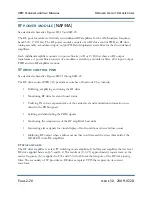
Power MOSFET Class 'D' Operation
Power MOSFETs can be used to replace
the switches as depicted in the simple class
'D' operation and push-pull class 'D'
operation examples. Note that the switch
contacts are replaced by the phase-
oriented secondaries of an RF drive
transformer. Q1 corresponds to S1-A, Q2
to S1-B, Q3 to S2-B and Q4 to S2-A, as
depicted in the push-pull class 'D'
operation example. Q1 and Q4 turn on/
off together and Q2 and Q3 turn on/off
together.
Summary of Contents for XR12
Page 2: ......
Page 4: ......
Page 8: ...XR12 Troubleshooting Manual Table of contents Page viii Issue 3 0 2009 07 28...
Page 12: ...XR12 Troubleshooting Manual Page xii Issue 3 0 2009 07 28...
Page 20: ...XR12 Troubleshooting Manual Page xx Issue 3 0 2009 07 28...
Page 100: ...XR12 Troubleshooting Manual Detailed Circuit Descriptions Page 2 32 Issue 3 0 2009 07 28...
Page 108: ...XR12 Troubleshooting Manual Parts Lists Page 3 8 Issue 3 0 2009 07 28...
Page 196: ......
Page 214: ...XR12 Troubleshooting Manual Reading Electrical Schematics Page 5 6 Issue 3 0 2009 07 28...
Page 223: ...Issue 3 1 2014 05 07 SD 9 Figure SD 9 NAPX05E 02 Dynamic Carrier Control PWB Sheet 1of 2...
Page 224: ...Issue 3 1 2014 05 07 SD 10 Figure SD 10 NAPX05E 02 Dynamic Carrier Control PWB Sheet 2 of 2...
Page 233: ...Issue 3 1 2014 05 07 SD 19 Figure SD 19 NAP34A RF Power Module Overall Sheet 1 of 2...
Page 234: ...Issue 3 1 2014 05 07 SD 20 Figure SD 20 NAP34A RF Power Module Modulator Stage Sheet 2 of 2...
Page 235: ...Issue 3 1 2014 05 07 SD 21 Figure SD 21 NAPC150A RF Drive Control PWB Sheet 1 of 3...
Page 236: ...Issue 3 1 2014 05 07 SD 22 Figure SD 22 NAPC150A RF Drive Control PWB Sheet 2 of 3...
Page 237: ...Issue 3 1 2014 05 07 SD 23 Figure SD 23 NAPC150A RF Drive Control PWB Sheet 3 of 3...
Page 238: ...Issue 3 1 2014 05 07 SD 24 Figure SD 24 NASM07H Modulator Assembly...
Page 239: ...Issue 3 1 2014 05 07 SD 25 Figure SD 25 NAA51A 03 RF Amplifier Assembly...
Page 245: ...Issue 3 1 2014 05 07 SD 31 Figure SD 31 NAPS10C RF Drive Power Supply PWB...
Page 248: ...Issue 3 0 2009 07 28 MD 1 Figure MD 1 XR12 Transmitter...
Page 257: ...Issue 3 0 2009 07 28 MD 10 Figure MD 10 NAPP02 01A RF Current Probe PWB...
Page 259: ...Issue 3 0 2009 07 28 MD 12 Figure MD 12 NAFP103 05 Forward Reflected Power Probe A1 DETAIL...
Page 263: ...Issue 3 0 2009 07 28 MD 16 Figure MD 16 NAPC150A RF Drive Control PWB...
Page 265: ...Issue 3 0 2009 07 28 MD 18 Figure MD 18 NASM07H Modulator Assembly...
Page 266: ...Issue 3 0 2009 07 28 MD 19 Figure MD 19 PA Input Output PWB 176 1065 04 and 05...
Page 267: ...Issue 3 0 2009 07 28 MD 20 Figure MD 20 NAA51A 03 RF Amplifier Assembly...
Page 268: ...Issue 3 0 2009 07 28 MD 21 Figure MD 21 NAPI47B Modulator Input Output PWB...
Page 271: ...Issue 3 0 2009 07 28 MD 24 Figure MD 24 Relay Assy 202 7019...
Page 272: ...Issue 3 0 2009 07 28 MD 25 Figure MD 25 Fan Tray 202 7020 J1 B1 B2...
Page 273: ...Issue 3 0 2009 07 28 MD 26 Figure MD 26 NAPS10C RF Drive Power Supply 62 V...
Page 275: ...Issue 3 0 2009 07 28 MD 28 Figure MD 28 Rectifier Assembly 202 7017...
Page 282: ......