


XR12 Troubleshooting Manual
Responding to alarms
Page 1-34
Issue 3.0 2009-07-28
5. Repeat
and
for the remaining suspect PAs. If any
C
or
G
waveform is not
satisfactory (rectangular wave, 0 to 24 V, assuming 50% duty cycle), the PA associated with
the unsatisfactory waveform is defective and must be replaced (see
6. Install a repaired or serviceable replacement PA in each vacant PA position, and then restart
the tests at
.
The following steps list the proper sequence for removing the power module from the transmitter's
test circuit.
7. Remove the jumper that connects TP2 to ground (TP3 or TP4) on the RF drive control
PWB that was installed in
. The
Block
(
A
,
B
,
C
and
D
) alarm LEDs will turn on.
8. On the front of the power module under test, press the
INHIBIT
button. The
TEMP/INHIBIT
alarm LED will turn on.
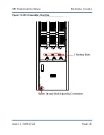
9. Remove the test cable's P3 plug from the power module's J1 connector. J1 is the connector
on the bottom of the power module near the front. Ignore all alarm indications.
10. Remove the test cable's P1 connector from the distribution PWB's J11 connector.
11. Remove the test cable's P4 plug from the power module's J2 connector. J2 is the lower
connector on the rear of the power module.
12. If repairs of the power module are complete, remove the test load from the power module's
J3 connector, and remove the test cable's P2 plug from the transmitter's RF drive splitter's J9
connector
If repairs on the power module are not complete, the test load and the test cable's
connection to the RF drive splitter can remain in place.
WARNING:
The power module must be removed from the transmitter's test circuit
before any sub-assembly is installed or removed from the power
module. Failure to do so can result in damage to the electronic
components in the power module.
It is important to remove the power module from the test circuit by
in the order they are listed to avoid
personal injury and damage to the power module.
Summary of Contents for XR12
Page 2: ......
Page 4: ......
Page 8: ...XR12 Troubleshooting Manual Table of contents Page viii Issue 3 0 2009 07 28...
Page 12: ...XR12 Troubleshooting Manual Page xii Issue 3 0 2009 07 28...
Page 20: ...XR12 Troubleshooting Manual Page xx Issue 3 0 2009 07 28...
Page 100: ...XR12 Troubleshooting Manual Detailed Circuit Descriptions Page 2 32 Issue 3 0 2009 07 28...
Page 108: ...XR12 Troubleshooting Manual Parts Lists Page 3 8 Issue 3 0 2009 07 28...
Page 196: ......
Page 214: ...XR12 Troubleshooting Manual Reading Electrical Schematics Page 5 6 Issue 3 0 2009 07 28...
Page 223: ...Issue 3 1 2014 05 07 SD 9 Figure SD 9 NAPX05E 02 Dynamic Carrier Control PWB Sheet 1of 2...
Page 224: ...Issue 3 1 2014 05 07 SD 10 Figure SD 10 NAPX05E 02 Dynamic Carrier Control PWB Sheet 2 of 2...
Page 233: ...Issue 3 1 2014 05 07 SD 19 Figure SD 19 NAP34A RF Power Module Overall Sheet 1 of 2...
Page 234: ...Issue 3 1 2014 05 07 SD 20 Figure SD 20 NAP34A RF Power Module Modulator Stage Sheet 2 of 2...
Page 235: ...Issue 3 1 2014 05 07 SD 21 Figure SD 21 NAPC150A RF Drive Control PWB Sheet 1 of 3...
Page 236: ...Issue 3 1 2014 05 07 SD 22 Figure SD 22 NAPC150A RF Drive Control PWB Sheet 2 of 3...
Page 237: ...Issue 3 1 2014 05 07 SD 23 Figure SD 23 NAPC150A RF Drive Control PWB Sheet 3 of 3...
Page 238: ...Issue 3 1 2014 05 07 SD 24 Figure SD 24 NASM07H Modulator Assembly...
Page 239: ...Issue 3 1 2014 05 07 SD 25 Figure SD 25 NAA51A 03 RF Amplifier Assembly...
Page 245: ...Issue 3 1 2014 05 07 SD 31 Figure SD 31 NAPS10C RF Drive Power Supply PWB...
Page 248: ...Issue 3 0 2009 07 28 MD 1 Figure MD 1 XR12 Transmitter...
Page 257: ...Issue 3 0 2009 07 28 MD 10 Figure MD 10 NAPP02 01A RF Current Probe PWB...
Page 259: ...Issue 3 0 2009 07 28 MD 12 Figure MD 12 NAFP103 05 Forward Reflected Power Probe A1 DETAIL...
Page 263: ...Issue 3 0 2009 07 28 MD 16 Figure MD 16 NAPC150A RF Drive Control PWB...
Page 265: ...Issue 3 0 2009 07 28 MD 18 Figure MD 18 NASM07H Modulator Assembly...
Page 266: ...Issue 3 0 2009 07 28 MD 19 Figure MD 19 PA Input Output PWB 176 1065 04 and 05...
Page 267: ...Issue 3 0 2009 07 28 MD 20 Figure MD 20 NAA51A 03 RF Amplifier Assembly...
Page 268: ...Issue 3 0 2009 07 28 MD 21 Figure MD 21 NAPI47B Modulator Input Output PWB...
Page 271: ...Issue 3 0 2009 07 28 MD 24 Figure MD 24 Relay Assy 202 7019...
Page 272: ...Issue 3 0 2009 07 28 MD 25 Figure MD 25 Fan Tray 202 7020 J1 B1 B2...
Page 273: ...Issue 3 0 2009 07 28 MD 26 Figure MD 26 NAPS10C RF Drive Power Supply 62 V...
Page 275: ...Issue 3 0 2009 07 28 MD 28 Figure MD 28 Rectifier Assembly 202 7017...
Page 282: ......