


XR12 Troubleshooting Manual
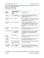
Responding to alarms
Page 1-18
Issue 3.0 2009-07-28
3. Use an oscilloscope to measure TP2 of the RF drive buffer PWB. The signal should be a 15
volt peak-to-peak square wave at the carrier frequency. If the signal is present, suspect the RF
drive buffer PWB.
4. Measure the dc voltage at TP1 of the RF drive buffer PWB. If the voltage is less than 0.6 V,
suspect the control/display PWB or transistor Q1 on the RF drive buffer PWB.
Cutback level (1-8)
Should there be three shutbacks within five seconds, the transmitter will enter a power reduction
mode called a cutback.
There are eight levels of cutbacks, the last being a reduction to no forward power whatsoever. At any
given cutback level, there is a predefined time limit that must expire before the cutback level is
reduced to the previous level. If there are no further cutbacks, this process continues until Level 0
(normal) is reached.
The cutback recovery process can be overridden by adjusting the power (up or down), or by pressing
Reset
on the
Status
screen.
A
Cutback Level (1-8)
status indicates that several shutback alarms (at least three shutbacks in five
seconds) have occurred. A cutback alarm may be triggered by a fault in the transmitter, large VSWR,
or a fault in the control/display PWB's microprocessor or alarm circuitry. Troubleshoot a cutback
alarm as follows:
1. Read the RF output power level on the
RF KILOWATTS
meter on the transmitter's front
panel.
2. Press/release the
Control - Power Increase
switch to clear the cutback alarm and to restore
the preset power level. If the fault persists, the output power will automatically cut back
again. Observe the
Events Log
and note which alarm is causing shutback. Refer to the
appropriate troubleshooting paragraph in this section.
Ext. PDM inhibit
The external PDM inhibit is wired to the remote interface PWB.
An
Ext. PDM Inhibit
alarm indicates that an external PDM inhibit command is present. The alarm
could be caused by an short circuit in the external wiring path to the remote control PWB, a fault in
the switching circuitry on the remote interface PWB, or a fault in the alarm circuitry on the control/
display PWB. Troubleshoot an
Ext. PDM Inhibit
alarm as follows:
Summary of Contents for XR12
Page 2: ......
Page 4: ......
Page 8: ...XR12 Troubleshooting Manual Table of contents Page viii Issue 3 0 2009 07 28...
Page 12: ...XR12 Troubleshooting Manual Page xii Issue 3 0 2009 07 28...
Page 20: ...XR12 Troubleshooting Manual Page xx Issue 3 0 2009 07 28...
Page 100: ...XR12 Troubleshooting Manual Detailed Circuit Descriptions Page 2 32 Issue 3 0 2009 07 28...
Page 108: ...XR12 Troubleshooting Manual Parts Lists Page 3 8 Issue 3 0 2009 07 28...
Page 196: ......
Page 214: ...XR12 Troubleshooting Manual Reading Electrical Schematics Page 5 6 Issue 3 0 2009 07 28...
Page 223: ...Issue 3 1 2014 05 07 SD 9 Figure SD 9 NAPX05E 02 Dynamic Carrier Control PWB Sheet 1of 2...
Page 224: ...Issue 3 1 2014 05 07 SD 10 Figure SD 10 NAPX05E 02 Dynamic Carrier Control PWB Sheet 2 of 2...
Page 233: ...Issue 3 1 2014 05 07 SD 19 Figure SD 19 NAP34A RF Power Module Overall Sheet 1 of 2...
Page 234: ...Issue 3 1 2014 05 07 SD 20 Figure SD 20 NAP34A RF Power Module Modulator Stage Sheet 2 of 2...
Page 235: ...Issue 3 1 2014 05 07 SD 21 Figure SD 21 NAPC150A RF Drive Control PWB Sheet 1 of 3...
Page 236: ...Issue 3 1 2014 05 07 SD 22 Figure SD 22 NAPC150A RF Drive Control PWB Sheet 2 of 3...
Page 237: ...Issue 3 1 2014 05 07 SD 23 Figure SD 23 NAPC150A RF Drive Control PWB Sheet 3 of 3...
Page 238: ...Issue 3 1 2014 05 07 SD 24 Figure SD 24 NASM07H Modulator Assembly...
Page 239: ...Issue 3 1 2014 05 07 SD 25 Figure SD 25 NAA51A 03 RF Amplifier Assembly...
Page 245: ...Issue 3 1 2014 05 07 SD 31 Figure SD 31 NAPS10C RF Drive Power Supply PWB...
Page 248: ...Issue 3 0 2009 07 28 MD 1 Figure MD 1 XR12 Transmitter...
Page 257: ...Issue 3 0 2009 07 28 MD 10 Figure MD 10 NAPP02 01A RF Current Probe PWB...
Page 259: ...Issue 3 0 2009 07 28 MD 12 Figure MD 12 NAFP103 05 Forward Reflected Power Probe A1 DETAIL...
Page 263: ...Issue 3 0 2009 07 28 MD 16 Figure MD 16 NAPC150A RF Drive Control PWB...
Page 265: ...Issue 3 0 2009 07 28 MD 18 Figure MD 18 NASM07H Modulator Assembly...
Page 266: ...Issue 3 0 2009 07 28 MD 19 Figure MD 19 PA Input Output PWB 176 1065 04 and 05...
Page 267: ...Issue 3 0 2009 07 28 MD 20 Figure MD 20 NAA51A 03 RF Amplifier Assembly...
Page 268: ...Issue 3 0 2009 07 28 MD 21 Figure MD 21 NAPI47B Modulator Input Output PWB...
Page 271: ...Issue 3 0 2009 07 28 MD 24 Figure MD 24 Relay Assy 202 7019...
Page 272: ...Issue 3 0 2009 07 28 MD 25 Figure MD 25 Fan Tray 202 7020 J1 B1 B2...
Page 273: ...Issue 3 0 2009 07 28 MD 26 Figure MD 26 NAPS10C RF Drive Power Supply 62 V...
Page 275: ...Issue 3 0 2009 07 28 MD 28 Figure MD 28 Rectifier Assembly 202 7017...
Page 282: ......