


XR12 Troubleshooting Manual
Wiring/connector lists
Issue 3.0 2009-07-28
Page 4-11
Source
Destination
Wire #
Colour
Size
Remarks
A14-D
A7-E
-
Inductor
12
L2 Leads
A14-F
A17-E
-
Inductor
12
L3 Leads
A14-J
A18-E
-
Inductor
12
L4 Leads
T1-A-1
A8G (+)
-
White
x2x18
T1 Lead
T1-A-
A8G (+)
-
White
x2x18
T1 Lead
T1-B-1
A8C (+)
-
White
x2x18
T1 Lead
T1-B-
A8C (+)
-
White
x2x18
T1 Lead
T1-C-1
A9G (+)
-
White
x2x18
T1 Lead
T1-C-
A9G (-)
-
White
x2x18
T1 Lead
T1-D-1
A9C (+)
-
White
x2x18
T1 Lead
T1-D-
A9C (-)
-
White
x2x18
T1 Lead
T1-1
J3-6/8
-
White
x2x18
T1 Lead
T1-2
J3-5/7
-
White
x2x18
T1 Lead
T2-A-1
A19G (+)
-
White
x2x18
T2 Lead
T2-A-
A19G (+)
-
White
x2x18
T2 Lead
T2-B-1
A19C (+)
-
White
x2x18
T2 Lead
T2-B-
A19C (+)
-
White
x2x18
T2 Lead
T2-C-1
A20G (+)
-
White
x2x18
T2 Lead
T2-C-
A20G (-)
-
White
x2x18
T2 Lead
T2-D-1
A20C (+)
-
White
x2x18
T2 Lead
T2-D-
A20C (-)
-
White
x2x18
T2 Lead
T2-1
J3-2/4
-
White
x2x18
T2 Lead
T2-2
J3-1/3
-
White
x2x18
T2 Lead
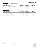
Table 4.9: NAP34A RF Power Module - Connector Mating Information
Connector
Mate
P1
A1A1
P2
A1J3
P3
A1J2
P4
A1J4
P6
A14J5
P7
A3J1
Table 4.8: Wiring List - NAP34A RF Power Module
Summary of Contents for XR12
Page 2: ......
Page 4: ......
Page 8: ...XR12 Troubleshooting Manual Table of contents Page viii Issue 3 0 2009 07 28...
Page 12: ...XR12 Troubleshooting Manual Page xii Issue 3 0 2009 07 28...
Page 20: ...XR12 Troubleshooting Manual Page xx Issue 3 0 2009 07 28...
Page 100: ...XR12 Troubleshooting Manual Detailed Circuit Descriptions Page 2 32 Issue 3 0 2009 07 28...
Page 108: ...XR12 Troubleshooting Manual Parts Lists Page 3 8 Issue 3 0 2009 07 28...
Page 196: ......
Page 214: ...XR12 Troubleshooting Manual Reading Electrical Schematics Page 5 6 Issue 3 0 2009 07 28...
Page 223: ...Issue 3 1 2014 05 07 SD 9 Figure SD 9 NAPX05E 02 Dynamic Carrier Control PWB Sheet 1of 2...
Page 224: ...Issue 3 1 2014 05 07 SD 10 Figure SD 10 NAPX05E 02 Dynamic Carrier Control PWB Sheet 2 of 2...
Page 233: ...Issue 3 1 2014 05 07 SD 19 Figure SD 19 NAP34A RF Power Module Overall Sheet 1 of 2...
Page 234: ...Issue 3 1 2014 05 07 SD 20 Figure SD 20 NAP34A RF Power Module Modulator Stage Sheet 2 of 2...
Page 235: ...Issue 3 1 2014 05 07 SD 21 Figure SD 21 NAPC150A RF Drive Control PWB Sheet 1 of 3...
Page 236: ...Issue 3 1 2014 05 07 SD 22 Figure SD 22 NAPC150A RF Drive Control PWB Sheet 2 of 3...
Page 237: ...Issue 3 1 2014 05 07 SD 23 Figure SD 23 NAPC150A RF Drive Control PWB Sheet 3 of 3...
Page 238: ...Issue 3 1 2014 05 07 SD 24 Figure SD 24 NASM07H Modulator Assembly...
Page 239: ...Issue 3 1 2014 05 07 SD 25 Figure SD 25 NAA51A 03 RF Amplifier Assembly...
Page 245: ...Issue 3 1 2014 05 07 SD 31 Figure SD 31 NAPS10C RF Drive Power Supply PWB...
Page 248: ...Issue 3 0 2009 07 28 MD 1 Figure MD 1 XR12 Transmitter...
Page 257: ...Issue 3 0 2009 07 28 MD 10 Figure MD 10 NAPP02 01A RF Current Probe PWB...
Page 259: ...Issue 3 0 2009 07 28 MD 12 Figure MD 12 NAFP103 05 Forward Reflected Power Probe A1 DETAIL...
Page 263: ...Issue 3 0 2009 07 28 MD 16 Figure MD 16 NAPC150A RF Drive Control PWB...
Page 265: ...Issue 3 0 2009 07 28 MD 18 Figure MD 18 NASM07H Modulator Assembly...
Page 266: ...Issue 3 0 2009 07 28 MD 19 Figure MD 19 PA Input Output PWB 176 1065 04 and 05...
Page 267: ...Issue 3 0 2009 07 28 MD 20 Figure MD 20 NAA51A 03 RF Amplifier Assembly...
Page 268: ...Issue 3 0 2009 07 28 MD 21 Figure MD 21 NAPI47B Modulator Input Output PWB...
Page 271: ...Issue 3 0 2009 07 28 MD 24 Figure MD 24 Relay Assy 202 7019...
Page 272: ...Issue 3 0 2009 07 28 MD 25 Figure MD 25 Fan Tray 202 7020 J1 B1 B2...
Page 273: ...Issue 3 0 2009 07 28 MD 26 Figure MD 26 NAPS10C RF Drive Power Supply 62 V...
Page 275: ...Issue 3 0 2009 07 28 MD 28 Figure MD 28 Rectifier Assembly 202 7017...
Page 282: ......