


XR12 Troubleshooting Manual
Detailed Circuit Descriptions
Issue 3.0 2009-07-28
Page 2-11
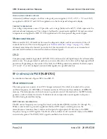
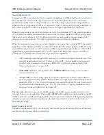
Figure 2.1: Timing Diagram for PDM Differential Amplifier
PDM2 generator
The PDM2 generator consists of U3C, U11B, Q6, Q7, and their associated components. It operates
similar to the PDM1 generator except U3C inverts the compensated
carrier ref + audio
input and
applies it to differential comparator U11B's inverting input. The result is a PDM2 'on period' when
the compensated
carrier ref + audio
is less positive than the triangular waveform and produces a
minimum 'on time' at the positive peaks of the triangular waveform. The on/off ratio of the
PDM1
and
PDM2
outputs are the same, but the zero power reference change for the
PDM2
output is offset,
relative to the
PDM1
output, by one half of the PDM repetition rate.
PDM fault detector
The PDM fault detector circuit contains two identical voltage controlled switches (one for each PDM
output) that control the 'set/'reset' status of the shutback latch circuit and, in turn, controls the on/
off status of relay K1. For explanation purposes, only the PDM1 fault detector is described.
The PDM1 fault detector circuit consists of U12A and its associated components. R67/C58 form an
integrator with a long time constant, relative to the PDM frequency. C58's charge voltage is applied to
U12A's inverting input and compared to the 7.3 V reference voltage applied to its non-inverting input
from voltage divider R70/R71/ R72. U12A's output is an open collector and has no influence when
C58's charge voltage is less positive than the reference voltage. U12A's output will switch to a
current-sink-to-ground when C58's charge voltage goes more positive than the reference voltage.
Inverted Carrier
Ramp
PDM 2
Reference Level
PDM 1
Ramp
Carrier Reference
Level
Summary of Contents for XR12
Page 2: ......
Page 4: ......
Page 8: ...XR12 Troubleshooting Manual Table of contents Page viii Issue 3 0 2009 07 28...
Page 12: ...XR12 Troubleshooting Manual Page xii Issue 3 0 2009 07 28...
Page 20: ...XR12 Troubleshooting Manual Page xx Issue 3 0 2009 07 28...
Page 100: ...XR12 Troubleshooting Manual Detailed Circuit Descriptions Page 2 32 Issue 3 0 2009 07 28...
Page 108: ...XR12 Troubleshooting Manual Parts Lists Page 3 8 Issue 3 0 2009 07 28...
Page 196: ......
Page 214: ...XR12 Troubleshooting Manual Reading Electrical Schematics Page 5 6 Issue 3 0 2009 07 28...
Page 223: ...Issue 3 1 2014 05 07 SD 9 Figure SD 9 NAPX05E 02 Dynamic Carrier Control PWB Sheet 1of 2...
Page 224: ...Issue 3 1 2014 05 07 SD 10 Figure SD 10 NAPX05E 02 Dynamic Carrier Control PWB Sheet 2 of 2...
Page 233: ...Issue 3 1 2014 05 07 SD 19 Figure SD 19 NAP34A RF Power Module Overall Sheet 1 of 2...
Page 234: ...Issue 3 1 2014 05 07 SD 20 Figure SD 20 NAP34A RF Power Module Modulator Stage Sheet 2 of 2...
Page 235: ...Issue 3 1 2014 05 07 SD 21 Figure SD 21 NAPC150A RF Drive Control PWB Sheet 1 of 3...
Page 236: ...Issue 3 1 2014 05 07 SD 22 Figure SD 22 NAPC150A RF Drive Control PWB Sheet 2 of 3...
Page 237: ...Issue 3 1 2014 05 07 SD 23 Figure SD 23 NAPC150A RF Drive Control PWB Sheet 3 of 3...
Page 238: ...Issue 3 1 2014 05 07 SD 24 Figure SD 24 NASM07H Modulator Assembly...
Page 239: ...Issue 3 1 2014 05 07 SD 25 Figure SD 25 NAA51A 03 RF Amplifier Assembly...
Page 245: ...Issue 3 1 2014 05 07 SD 31 Figure SD 31 NAPS10C RF Drive Power Supply PWB...
Page 248: ...Issue 3 0 2009 07 28 MD 1 Figure MD 1 XR12 Transmitter...
Page 257: ...Issue 3 0 2009 07 28 MD 10 Figure MD 10 NAPP02 01A RF Current Probe PWB...
Page 259: ...Issue 3 0 2009 07 28 MD 12 Figure MD 12 NAFP103 05 Forward Reflected Power Probe A1 DETAIL...
Page 263: ...Issue 3 0 2009 07 28 MD 16 Figure MD 16 NAPC150A RF Drive Control PWB...
Page 265: ...Issue 3 0 2009 07 28 MD 18 Figure MD 18 NASM07H Modulator Assembly...
Page 266: ...Issue 3 0 2009 07 28 MD 19 Figure MD 19 PA Input Output PWB 176 1065 04 and 05...
Page 267: ...Issue 3 0 2009 07 28 MD 20 Figure MD 20 NAA51A 03 RF Amplifier Assembly...
Page 268: ...Issue 3 0 2009 07 28 MD 21 Figure MD 21 NAPI47B Modulator Input Output PWB...
Page 271: ...Issue 3 0 2009 07 28 MD 24 Figure MD 24 Relay Assy 202 7019...
Page 272: ...Issue 3 0 2009 07 28 MD 25 Figure MD 25 Fan Tray 202 7020 J1 B1 B2...
Page 273: ...Issue 3 0 2009 07 28 MD 26 Figure MD 26 NAPS10C RF Drive Power Supply 62 V...
Page 275: ...Issue 3 0 2009 07 28 MD 28 Figure MD 28 Rectifier Assembly 202 7017...
Page 282: ......