Dimensions = mm (inches)
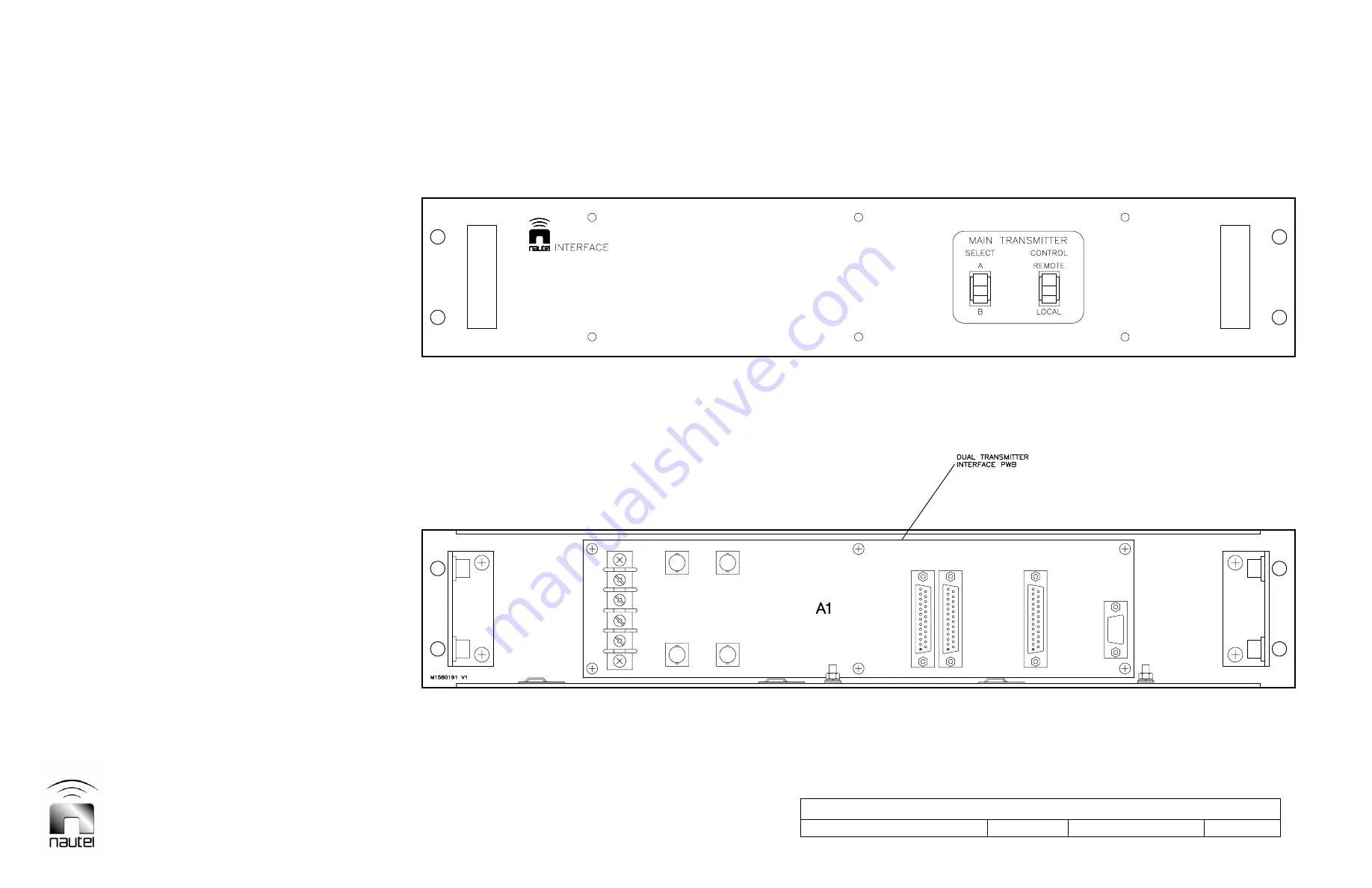
Figure 5 - Assembly Detail – NAX223 Dual Transmitter Interface Assembly
Version 1.0
Not to Scale
Drawing No. M1580191
Sheet 1 of 1
Page 1: ...autel Limited 10089 Peggy s Cove Road Hackett s Cove NS Canada B3Z 3J4 T 1 902 823 2233 F 1 902 823 3183 info nautel com U S customers please contact Nautel Maine Inc 201 Target Industrial Circle Bang...
Page 2: ...th transmitters A ND500II 11x x2x and B ND500II 01x x2x The following provides a brief description for transmitters that are connected in a main standby dual installation See figure 2A or 2B for inter...
Page 3: ...by transmitter is on g If transmitter B is selected as the main transmitter an open collector SHTDN ALM B signal will be applied to 3A1J5 23 from A11J4 17 shutdown of transmitter B causing a ground to...
Page 4: ...onnect BNC connector P1 to A1J7 Connect BNC connector P4 to A1J6 Connect wire 45 to A1TB4 3 Connect wire 46 to A1TB4 4 Connect wire 47 to A1TB4 3 Connect wire 48 to A1TB4 4 Secure the cableform to the...
Page 5: ...of transmitter A o Re install rear covers on transmitters A and B that were removed in step e 5 INITIAL START UP PROCEDURES Transmitters A and B should not be fully operated as a dual transmitter sys...
Page 6: ...e harness and should not be used for connection between transmitter B and an external dummy load A user provided coaxial cable should be obtained f Set transmitter B s LOCAL REMOTE switch to LOCAL g S...
Page 7: ...ginal connections p Remove jumper connected in step c q Set POWER switch of both transmitters to ON and set their LOCAL REMOTE switches to the desired position 7 CHECK OF CHANGEOVER UNIT Check the ope...
Page 8: ...C is used as voltage source for external SWR ALARM and BATTERY STATUS circuits connect circuit VDC to 3A1TB2 8 3A1J1 2 If an external DC power supply is used as voltage source for external SWR ALARM a...
Page 9: ...3 P2 11 14 White 22 P6 14 P2 7 15 White 22 1 Conductor P6 15 P2 19 15 Shield 22 Shielded P6 16 P2 8 16 Black 22 P6 17 P2 23 17 White 22 P6 18 P2 9 18 White 22 P6 19 P2 6 19 White 22 P6 20 P2 2 20 Whit...
Page 10: ...49 Grn Yel 14 User Cabinet Safety Ground 2 Safety Ground 50 Grn Yel 14 Additional wiring when remote control unit unit 4 is used P12 3 P13 36 100 White 22 P12 4 4TB1 1 101 White 22 P12 5 P13 24 102 Wh...
Page 11: ...m Crimp JDP24 225395 7 09482 P2 Connector D Sub 25 Socket 183 5010 183 5010 37338 P3 Connector D Sub 25 Socket 183 5010 183 5010 37338 P4 Connector Coaxial BNC Plug 50ohm Crimp JDP24 225395 7 09482 P5...
Page 12: ...PWB JS43 163A16279X 31781 J6 Connector BNC Receptacle PWB Mt JF35 R141 426 000 0GP12 J7 Connector BNC Receptacle PWB Mt JF35 R141 426 000 0GP12 J8 Conn Socket D Sub 9 Pin Vertical PWB JS50 164A16669X...
Page 13: ...14 19 16 15 A7J2 P11 2 17 1 XMTR A A11J4 5 9 7 6 1 1 18 A11J4 8 INCREASE A DECREASE A 15VDC ATU A GND A SERVO INHB A RMT SHTDN ALM A B VDC A 24VDC A RMT SWR ALM A 13 23 9 24 15 16 17 1 14 GND A RMT AU...
Page 14: ...ION 1 GND A DC SUPPLY DC SUPPLY 1 2 A11TB2 22 12 20 21 3 4 A11J4 XMTR A RMT ON OFF A RMT PWR TRIM A STBY ON OFF A STBY 2 A STBY 1 A A11J4 1 7 9 6 RMT SHTDN ALM A DECREASE A 15VDC ATU A GND A SERVO INH...
Page 15: ...R5 1 13 J1 1 16 K1 E 3 5 7 K1 A 1 12 J1 1 16 K2 E CR6 3 5 7 K2 A 13 11 9 K1 C 4 6 8 K1 B 1 2 RMT XMTR ON STAT 9 4 J1 B VDC 1 2 3 NO COM NC RMT SHTDN ALM 3 J1 19 J1 6 15VDC B STBY ON OFF A 2 J4 RMT ON...
Page 16: ...Dimensions mm inches Figure 4 Assembly Detail Dimensional Information Dual ND500II Transmitters User Supplied Cabinet Version 1 0 Not to Scale Drawing No M1580198 Sheet 1 of 1...
Page 17: ...Dimensions mm inches Figure 5 Assembly Detail NAX223 Dual Transmitter Interface Assembly Version 1 0 Not to Scale Drawing No M1580191 Sheet 1 of 1...
Page 18: ...Dimensions mm inches Figure 6 Assembly Detail NAPI66 Dual Transmitter Interface PWB Version 1 0 Not to Scale Drawing No M1580175 Sheet 1 of 1...