background image

User Manual / CONVERTISS FOLDING PREMIUM

Made by NAUSICAA Medical S.A.S. / Approved by Ghizlane Labrosse (Biomedical Engineer)

Fitting the side rails

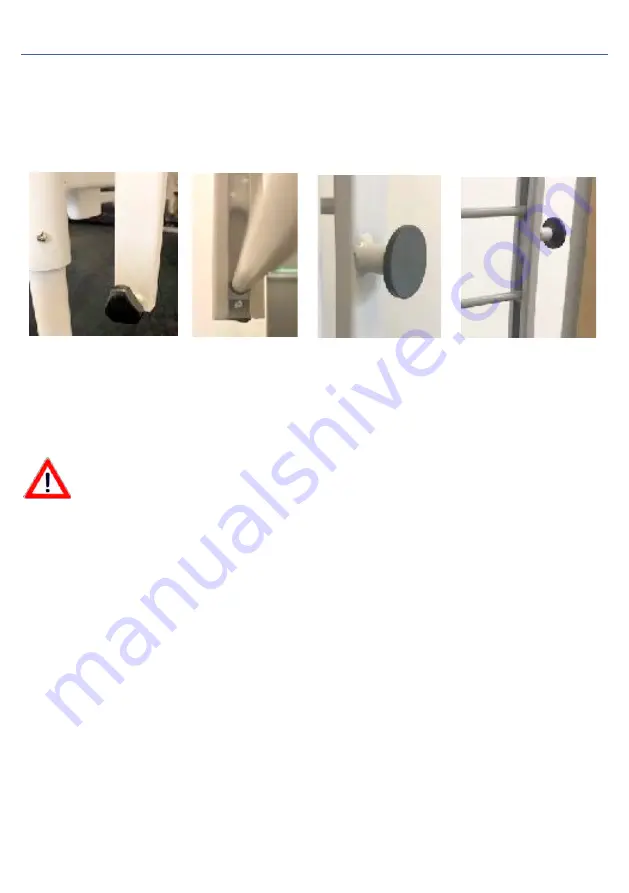
1. Unscrew the small thumb turn screw at the bottom of each runner.

2. Slide the top of each end of the side rails into the channels on both ends of the bed until the bottom is above the thumb 

turn and tighten to prevent the side rails from falling out of the bottom of the channel.

Lowering and Raising

3. To raise the rails, simply lift the rails in the runners on both sides of the bed past the black locking pin until it clicks.

4. To lower the rails, pull out the black locking pin to release the side rails and lower them down on both ends of the bed. 

You may need to lift slightly before pulling out the pin.

11

The main control box comes already attached to the 
knee break actuator with all the cables for the 
actuators and the handset connected.

The knee break actuator should be mounted under 
the bed frame so that the motor end (the end where 
the cables connects to the actuator) is towards the 
centre of the bed and the extending ram of the 
actuator is connected to the moving knee break 
section of the mattress platform.

In order to insert the securing pin into the end of the 
extending ram you need to manually lift the knee 
break and pull out the ram so that it is away from the 
control box it is attached to, allowing you to insert the 
locking pin. Please see image to the left.

The backrest actuator should then be mounted under the bed frame again so that the 
motor end is towards the centre of the bed and the extending ram is connected to the 
moving back rest section of the mattress platform.

Ensure all mounting pins are fully inserted through the bed frame mounting points on both 
sides of the actuator and the spring loaded locking loops are in the closed position.

All the cables should be already attached to the control box and numbered 1 – 4 with a 
tag on the opposite end where they connect into each actuator. The number inside the 
control box (re circles above) should correspond with the same number on the other end 
of each cable.

Number 1 cable should be connected into the backrest actuator.
Number 2 cable should be connected into Hi-Lo actuator at the foot end of the bed.
Number 3 cable should be connected into the backrest actuator.
Number 4 cable should be connected into the Hi-Lo actuator at the head end of the bed.   

Pay attention to position the back and foot rest actuators correctly! They should 
never be inverted.

Special safety rules for the bed rails.

The bed rails are there to protect patients from possible accidental falls from the bed. However, they 

cannot prevent the patient from voluntarily leaving the bed. To make the best use of their intended 

protection function, please observe the following precautions:

Use only undamaged bed rails and in good conditions positioned at the right distance to allow the rails to snap into 

place properly.

• Make sure to use only the Apollo original bed rails supplied with the bed.

• When using a bed with bed rails you must always verify if they are suitable for each individual patient. In particular, 

it is necessary to pay attention to the distance between the bars in relation to the patients’ body build. If they are 

very skinny and thin it could be necessary to use some padding or pads around the bed rails (optional). Only in this

way will it be safe to use the bed without the risk of the patient to be caught or to slide out of the bed rails.

• The mechanical elements which attach the bed and the rails should be checked regularly to make sure there are no 

signs of damage. This must be done not only before applying the bed rails, but also during use within short intervals 

(at least before any new use).

• When applying the bed rails to the electric bed always make sure to block the backrest and leg supports with 

the hand control to protect the patient from any accidental electric movements (risk of involuntarily crushing the 

patient’s limbs).

Failure to comply with the above safety rules will lead to the possible risks of the patient getting caught in the bed rails, 

falling out of the bed if the bed rails are too wide due to possible damages, in case they are not the correct bed rails for 

the electric bed or if they have not been mounted and inserted correctly.

4. FUNCTIONING

12

16 


4.7 Barrières latérales de lit 
 
 
Si vous souhaitez avoir des barrières latérales, alors vous devrez installer de chaque côté (en 
option) les rails à la tête et au pied du lit. Ceux-ci peuvent rester en place, mais les longerons 
eux-mêmes doivent être retirés avant de replier le lit. 
 
Montage des glissières 
1. Retirez les capuchons en plastique noir et vert du haut de chaque côté de la tête et du repose-
pieds. 
2. Retirez le boulon de la clé Allen de la plaque de montage adjacente au sommier du matelas de 
chaque côté de la tête et de pieds. 
3. Insérez les glissières dans la partie supérieure de la tête et des pieds et fixez-les avec les vis à 
tête hexagonale en haut et en bas. 

3 


Les barrières latérales 
 1. Dévissez la petite vis du pouce située au bas de chaque glissière. 
2. Faites glisser le haut de chaque extrémité des barrières latérales dans les rainures situées aux 
deux extrémités du lit jusqu'à ce que le fond dépasse le pouce et serrez-les pour éviter que les 
barrières latérales ne tombent du bas du chenal. 


4 

Summary of Contents for CONVERTISS FOLDING PREMIUM

Page 1: ...3485 www nausicaa medical com User Manual CONVERTISS FOLDING PREMIUM Made by NAUSICAA Medical S A S Approved by Ghizlane Labrosse Biomedical Engineer MANUFACTURING STEEL MAXIMUM PATIENT WEIGHT 180 kg CLASS 1 MEDICAL DEVICE ALL OUR DEVICES COMPLYWITH NF EN ISO 60601 2 52 2010 ...

Page 2: ... NAUSICAA Medical S A S Approved by Ghizlane Labrosse Biomedical Engineer 1 HEAD PANEL 2 METAL 4 BAR BED RAILS not shown 3 HAND CONTROL 4 BED RAIL RELEASE LEVER 5 FOOT PANEL 6 WHEELS WITH BRAKE 7 HOUSING FOR LIFTING POLE ON BOTH SIDES 4 5 2 1 3 6 7 ...

Page 3: ...1 Special safety warnings 4 2 Hand control 4 2 1 Hand control use 4 3 Swivel wheels 4 4 Lifting Pole 4 5 Bed Lever 4 6 Dynamic Mattress 4 7 Bed Rails 4 8 Bed End Panels 5 CLEANING AND DISINFECTING 5 1 General information 5 2 Cleaning and disinfection program 5 3 Training of users 5 4 Detergents and disinfectants 5 4 1How to use disinfectants 6 MAINTENANCE 6 1 By the user 6 2 By the owner 6 3 Spare...

Page 4: ...ity of each bed has been extensively tested by the manufacturer in order to avoid any faults This manual provides useful information to the buyer and to the end user on all the functions which will allow a safe and practical daily use of this bed Therefore we recommend you to use this manual as a handy guide and to keep it near your bed In the hope that for you and for the users of this nursing be...

Page 5: ...he nursing bed is a high technology product therefore make sure to read the complete manual when delivered Make sure to use the nursing bed only if it is in good condition The goal of the safety warnings is to avoid injuries to people 2 2 1 SAFETY SYMBOLS USED The following symbols appear in this manual Warnings against injuries This symbol indicates the presence of dangerous power voltage which c...

Page 6: ...of his her training experience or education and who has been trained to use the bed Furthermore the user must be able to perform basic safety checks on the bed and also be able to recognise and avoid potential hazards as well as evaluating the condition of the patient Patient In this manual the term patient refers to the person who needs to be taken care of who might be sick or disabled and theref...

Page 7: ...are made of wood or similar material whose surface is waterproof The surfaces are not harmful in contact with the skin 2 3 4 FRAME The bed is supplied part assembled to be easily transported into the house It is made up of the bed frame with wooden panel inserts head panel and foot panel a mattress base with a motor a pantograph mechanism with an electric actuator two four bar metal bed rails and ...

Page 8: ...ed locking loops are in the closed position All the cables should be already attached to the control box and numbered 1 4 with a tag on the opposite end where they connect into each actuator The number inside the control box re circles above should correspond with the same number on the other end of each cable Number 1 cable should be connected into the backrest actuator Number 2 cable should be c...

Page 9: ...l box re circles above should correspond with the same number on the other end of each cable Number 1 cable should be connected into the backrest actuator Number 2 cable should be connected into Hi Lo actuator at the foot end of the bed Number 3 cable should be connected into the backrest actuator Number 4 cable should be connected into the Hi Lo actuator at the head end of the bed Pay attention t...

Page 10: ...ing third party accessories could restrict the moving parts of the bed The warranty does not cover any damages caused by use of third party accessories and your warranty could be void if third party accessories are installed and used 3 2 Operations Every time before using the bed the user must make sure that the wheels of the bed are locked see also chapter 4 3 the power supply is compatible with ...

Page 11: ...art of the bed is restricted from moving freely as it should In case of questions or doubts please contact the manufacturer of such accessories 2 GENERAL INFORMATION Before using the bed Read through this whole manual in order to avoid causing damages to the bed due to improper use Before using the nursing bed the user must verify its perfect functional status and complete efficiency This bed conf...

Page 12: ...arquet floor make sure that the use of wheels will not cause any discolouring due to the parquet waterproof treatment It is possible to use the bed on tiles carpets laminated floors and linoleum A 230 volt power outlet correctly installed must be located as near as possible to the bed If there is the need to use other accessories such as compressor systems bed levers etc make sure they are correct...

Page 13: ...r make sure that the use of wheels will not cause any discolouring due to the parquet waterproof treatment It is possible to use the bed on tiles carpets laminated floors and linoleum A 230 volt power outlet correctly installed must be located as near as possible to the bed If there is the need to use other accessories such as compressor systems bed levers etc make sure they are correctly fixed an...

Page 14: ...hey should never be inverted Special safety rules for the bed rails The bed rails are there to protect patients from possible accidental falls from the bed However they cannot prevent the patient from voluntarily leaving the bed To make the best use of their intended protection function please observe the following precautions Use only undamaged bed rails and in good conditions positioned at the r...

Page 15: ... liquids which might lead to malfunctioning or damages to the electric components 12 Make sure not to damage any cables Verify that the cables are not tangled and that they are not able to get caught in any in moving parts during use In case of replacement of any individual components always make sure that the electric plugs are then properly inserted into the controller Only in this way will the ...

Page 16: ...y the specialised staff even the normal day to day users such as nurses assistants etc must perform both a visual and a functional inspection before each new use and at regular intervals Recommendation check all mechanical and electrical components once a month In addition check the power cord and the hand control cable after each mechanical stress and after each change of position Therefore it is...

Page 17: ...sed again until the damaged components have been totally replaced or repaired To replace or repair damaged parts please contact the owner of the bed 6 2 By the owner 11 The main control box comes already attached to the knee break actuator with all the cables for the actuators and the handset connected The knee break actuator should be mounted under the bed frame so that the motor end the end wher...

Page 18: ...e cables should be already attached to the control box and numbered 1 4 with a tag on the opposite end where they connect into each actuator The number inside the control box re circles above should correspond with the same number on the other end of each cable Number 1 cable should be connected into the backrest actuator Number 2 cable should be connected into Hi Lo actuator at the foot end of th...

Page 19: ...amages chips Knobs Correct fixing Worn out parts such as the hinged points Damages II Electrical measurement in accordance with VDE 0751 1 2001 10 power from the device direct Proceed as follows ok not ok Problem description 1 Insert the power cord of the bed into the testing outlet of the measuring device 2 Connect the probe of the measuring device to a free conductor element of the frame such as...

Page 20: ...onnecting cable properly fixed Functional control of the mechanical components Hinged and pivot points Working smoothly casters Brakes moving forwards Bed rails Locking and unlocking mechanisms Knee raiser Hinge point Accessories ex Trapeze bar handle Mounting damages suitability Inspection result All values within the allowed range yes no Next inspection date The test was passed yes no If the tes...

Page 21: ...are parts supplied by NAUSICAA Médical Ltd To order spare parts for any requests or assistance and for further information please contact Lits Verticalisateurs Lève Personnes Releveur Mobile Lève Personnes Mobile Téléphone 04 66 71 71 80 Fax 04 66 71 71 81 Mail sav nausicaa medical com 6 4 Electrical components replacement Dangerous for your life life threat due to electric shock Before starting a...

Page 22: ...m the owner and ask for repairs Pressing the keys the movements are activated only for a short time Too much weight on the bed The bed hits against an obstacle Reduce the load Remove the obstacle Movement in one direction only Defective hand control or operating console Inform the owner and ask for repairs Function in contrast with the instruction on the hand control Reversed motor connectors Info...

Page 23: ...vice Main Control Unit Type Linak CA4 Series Control Unit Input voltage AC 230 V 10 50 60 Hz Classification Class II Hand control Type Linak 10 button with individual lock outs Electric motors for height adjustment of the mattress base and backrest and footrest Type Linak LA27 Series Linear Actuators Minimum Average speed at full load mm s 4 5 5 5 8 3 Environmental conditions Noise during adjustme...

Page 24: ...User Manual CONVERTISS FOLDING PREMIUM Made by NAUSICAA Medical S A S Approved by Ghizlane Labrosse Biomedical Engineer 22 POTENCE POUR CONVERTISS 5F et 6F POTC 00001 165 9 LABELLING ...

Page 25: ...rranty does not apply if the claims are consecutive to accident misuse or neglect of the unit by the end customer shipping performed without adequate protection alteration or transformation not validated by NAUSICAA Médical S A S the impact of external elements natural disaster fire shock humidity flood lightning installation and or use in a non compliant way with technical standards and safety in...

Page 26: ...24 User Manual CONVERTISS FOLDING PREMIUM Made by NAUSICAA Medical S A S Approved by Ghizlane Labrosse Biomedical Engineer ...

Page 27: ...25 User Manual CONVERTISS FOLDING PREMIUM Made by NAUSICAA Medical S A S Approved by Ghizlane Labrosse Biomedical Engineer ...

Page 28: ...éléphone 04 66 51 50 80 Fax 04 66 51 50 47 Mail contact nausicaa medical com www nausicaa medical com Votre correspondant Manufactured by NAUSICAA Médical S A S 12 Allée du Piot ZA Pôle Actif 30660 Gallargues le Montueux FRANCE ...

Reviews: