


SCXI Quick Start Guide
16
ni.com
Note
Some M Series devices have two connectors. You must select the range of
channels that corresponds to the connector cabled to the module. Channels 0–7
correspond to connector 0. Channels 16–23 correspond to connector 1.
Caution
If you remove a chassis from a daisy chain, reassign the index values for
modules in other chassis. Reassigning values maintains consistency and prevents
addressing removed chassis.
17. Click
OK
to accept the settings, close the Details window, and return to the SCXI Chassis
Configuration window.
18. If you installed more than one module, repeat the configuration process from step 6 by
selecting the appropriate SCXI module from the next
Module Array
listbox.
19. If you need to change any chassis settings, click the
Chassis
tab.
20. Click
OK
to accept and save the settings for this chassis.
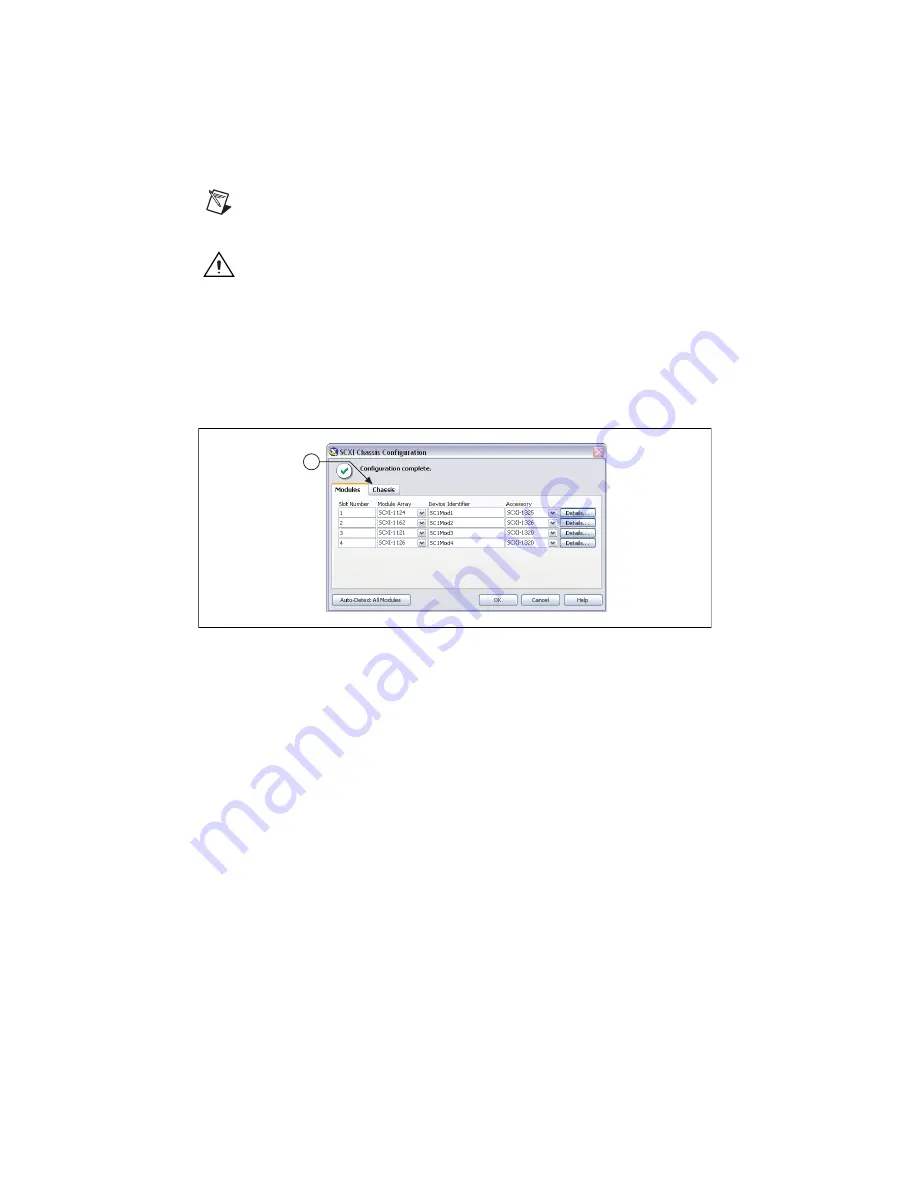
A message at the top of the SCXI Chassis Configuration window displays the status of the
configuration. You cannot save the chassis configuration if an error appears until you finish
entering module information. If a warning appears, you can save the configuration, but NI
recommends that you correct the source of the warning first.
21. For IEEE 1451.4 transducer electronic data sheet (TEDS) sensors and accessories,
configure the device and add the accessory as described in these steps. To configure TEDS
sensors cabled directly to a device, in MAX, right-click the module under
Devices and
Interfaces
and select
Configure TEDS
. Click
Scan for HW TEDS
in the configuration
window.
Add Modules to an Existing System
Complete the following steps:
1.
Expand
Devices and Interfaces
. If you are using a remote RT target, expand
Remote
Systems
, find and expand your target, and right-click
Devices and Interfaces
.
2.
Click the chassis to display a list of slots.
3.
Right-click an empty slot and select
Insert
. The SCXI Chassis Configuration window
opens.
19
Summary of Contents for SCXI-116 Series
Page 1: ...SCXI 1143...