©
National Instruments Corporation
9
SCXI Quick Start Guide
•
If all modules are in parallel mode, attach a cable adapter to each module. The
following modules can run in parallel mode:
2.
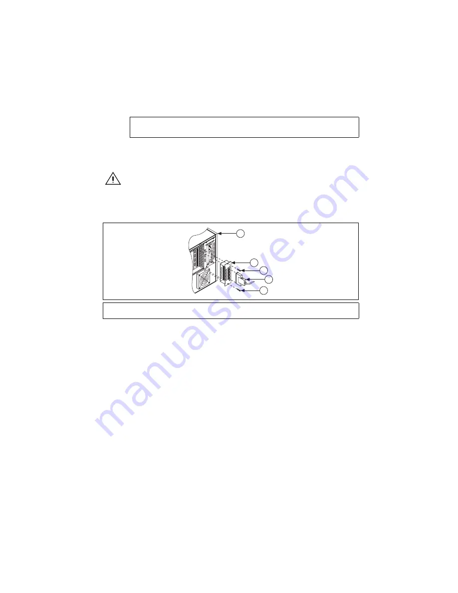
Insert the 50-pin female connection on the rear of the cable adapter into the 50-pin male
connector on the rear of the appropriate SCXI module.
Caution
Do
not
force the adapter if there is resistance. Forcing the adapter can bend
pins.
3.
Fasten the adapter to the rear of the SCXI chassis with the screws provided with the
SCXI-1349.
Figure 10.
Installing the Cable Adapter
Multichassis System
The SCXI-1346 covers the rear connector of two modules. When viewing the chassis from the
rear, the module to the right of the module directly connected to the SCXI-1346 cannot have an
external cable inserted into its rear 50-pin connector.
SCXI-1000 chassis through revision D do not have address jumpers or switches and respond to any
address, but you cannot use them in multichassis systems. Revision E chassis use jumpers on Slot
0 for chassis addressing. Revision F and later chassis use a DIP switch for chassis addressing.
SCXI-1000DC chassis through revision C do not have address jumpers or switches and respond
to any address, but you cannot use them in multichassis systems. Revision D and later chassis
use jumpers on Slot 0 for chassis addressing.
SCXI-1001 chassis through revision D use jumpers on Slot 0 for chassis addressing. Revision E
and later chassis use a DIP switch for chassis addressing.
SCXI-1120/D, SCXI-1121, SCXI-1125, SCXI-1126, SCXI-1140, SCXI-1141, SCXI-1142,
SCXI-1143, SCXI-1520, SCXI-1530, SCXI-1531
1
SCXI Chassis
2
SCXI-1349 Cable Adapter
3
6
8
-Pin Shielded Cable
4
Screws
1
3
2
4
4
FU
S
E
PULL
Summary of Contents for SCXI-116 Series
Page 1: ...SCXI 1143...


