


NI PXIe-4353 and TB-4353 Terminal Block Installation Guide
10
ni.com
Configure a Task Using the DAQ Assistant from MAX
Complete the following steps to create a task using the DAQ Assistant in MAX:
1.
In MAX, right-click
Data Neighborhood
and select
Create New
to open the DAQ Assistant.
2.
Select
NI-DAQmx Task
and click
Next
.
3.
Select
Acquire Signals
.
Note
The NI PXIe-4353 cannot generate signals.
4.
Select
Analog Input
and the measurement type, such as
Temperature
»
Thermocouple
or
Voltage
.
5.
Select the physical channel(s) to use and click
Next
.
6.
Name the task and click
Finish
.
7.
Configure the individual channel settings. Each physical channel you assign to a task receives a
virtual channel name. To modify the input range or other settings, select the channel. Click
Details
for physical channel information. Configure the timing and triggering for your task. Click
Run
.
Step 8. Use Your NI SC Express 4353 in an Application
For NI software version compatibility, refer to the NI-DAQmx Readme, available from
Start»
All Programs»National Instruments»NI-DAQmx
.
To get started with data acquisition in your application software, refer to the tutorials listed in Table 1.
Programming Examples
NI-DAQmx includes example programs to help you get started developing an application. LabVIEW
and CVI examples are located at
Help»Find Examples
in your application software. Text-based code
examples are located at
All Programs»National Instruments»NI-DAQ»Text-Based Code Support»
ANSI C Examples
. Modify example code and save it in an application, or use examples to develop a
new application or add example code to an existing application.
For other examples, go to
ni.com/info
and enter the Info Code
daqmxexp
. For additional examples,
refer to
zone.ni.com
.
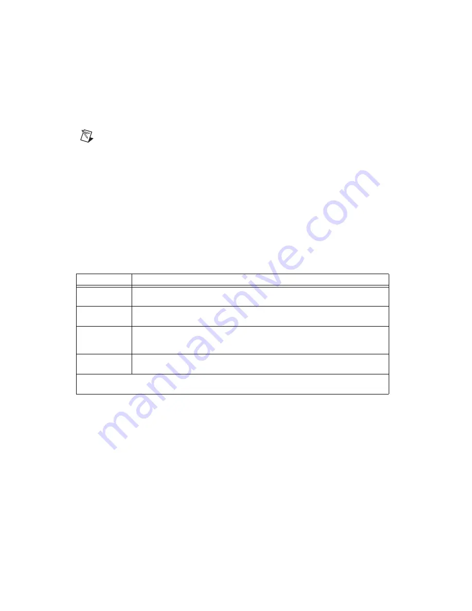
Table 1.
DAQ Assistant Tutorial Locations
Application
Tutorial Location
LabVIEW
Go to
Help»Search the LabVIEW Help
. Next, go to
Getting Started with LabVIEW»
Getting Started with DAQ»Taking an NI-DAQmx Measurement in LabVIEW
.
LabWindows/CVI
Go to
Help»Contents
. Next, go to
Using LabWindows/CVI»Data Acquisition»Taking an
NI-DAQmx Measurement in LabWindows/CVI
.
Measurement
Studio
Go to
NI Measurement Studio Help»Getting Started with the Measurement Studio Class
Libraries»Measurement Studio Walkthroughs»Walkthrough: Creating a Measurement Studio
NI-DAQmx Application
.
LabVIEW
SignalExpress
*
Go to
Help»Taking an NI-DAQmx Measurement in SignalExpress
.
*
LabVIEW SignalExpress, an easy-to-use configuration-based tool for data logging applications, is at
Start»
All Programs»National Instruments»LabVIEW SignalExpress
.


