background image

Getting Started NI SMD-7613/7614/7615/7616 Stepper Drives

|

© National Instruments

|

3

Hardware Installation and Configuration

This section covers the hardware setup for the NI SMD-7613/7914/7615/7616 device.

Step 1: Connect the Drive to the NI PS-12/13 Power 
Supply

Note

Do not plug in or turn on the power supply until after you complete all of the 

following steps.

Complete the following steps to connect the power supply to AC input power and to the drive. 

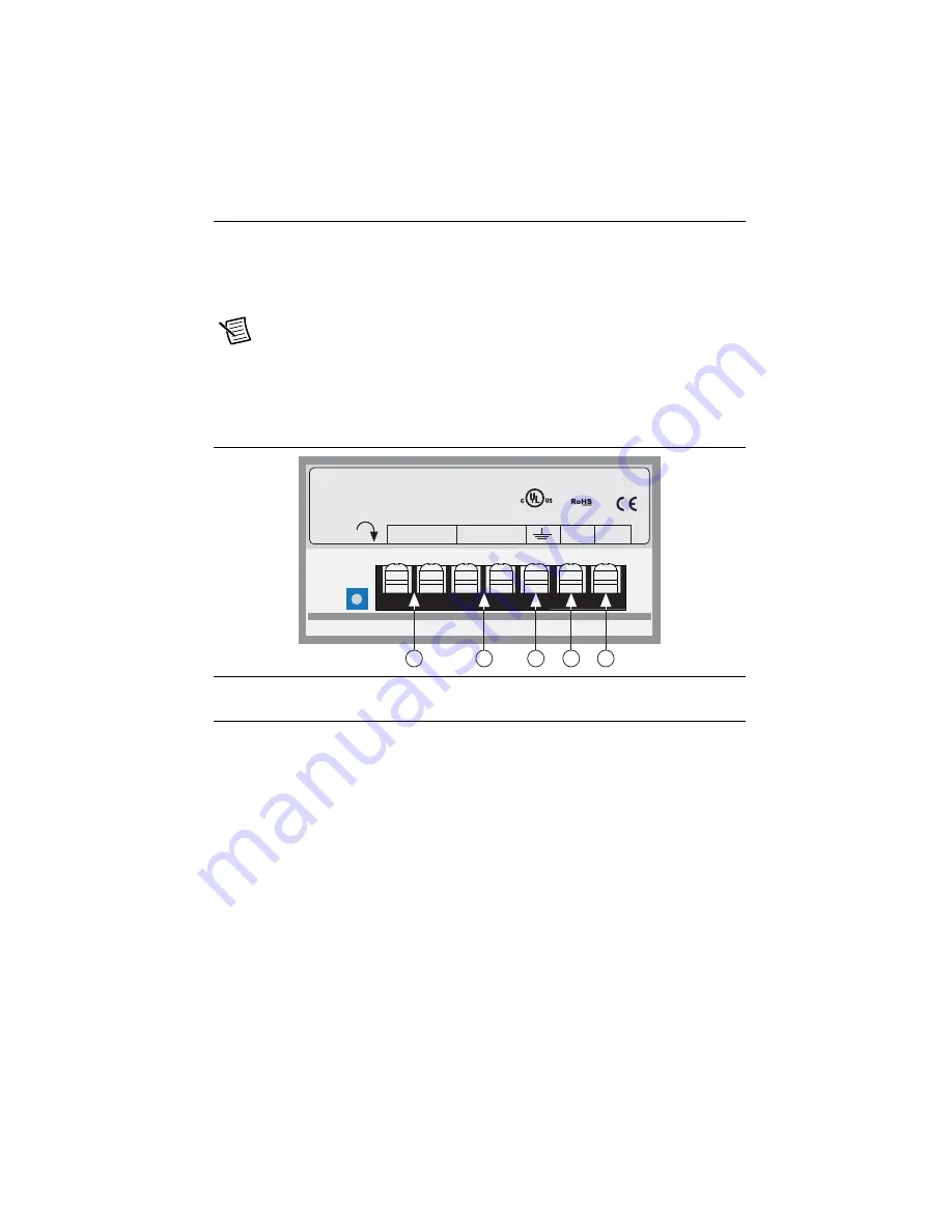
Figure 1 shows the power supply terminals.

Figure 1.  

NI PS-12/13 Power Supply Terminals

1. Connect an AC input cable to the line, neutral, and ground (protective earth) connectors.
2. Connect one end of a 1.02 mm to 0.81 mm diameter (18 to 20 AWG) gauge stranded wire 

to the V+ terminal on the power supply.

3. Connect the free end of the V+ wire to the corresponding terminal on the included power 

connector. Tighten the screw to ensure a secure connection.

4. Connect one end of a 1.02 mm to 0.81 mm diameter (18 to 20 AWG) gauge stranded wire 

to the V- terminal on the power supply. 

5. Connect the free end of the V- wire to the corresponding terminal on the included power 

connector. Tighten the screw to ensure a secure connection.

6. Insert the power connector into the stepper motor drive. Tighten the screws to ensure a 

secure connection.

7. Connect the power supply to AC power. The green Drive Status LED on the SMD should 

be solid or flashing. For information about blink code meanings, refer to the user manual 

for your device.

1

+24 V (NI PS-12) or +48 V (NI PS-13) Output

2

+24 V (NI PS-12) or +48 V (NI PS-13) Ground

3

AC Input Ground (Protective Earth)

4

AC Input Neutral

5

AC Input Line

L

N

-V

+V

Made in China

+V  ADJ

+

OUTPUT: 48V      6.7A

INPUT: 100-240VAC 5A 50/60Hz

L

N

-V

+V

M

a

de in Chin

a

+V  ADJ

+

Serial No.

1

2

3

4

5

Summary of Contents for NI SMD-7613

Page 1: ...and Configuration 3 Step 1 Connect the Drive to the NI PS 12 13 Power Supply 3 Step 2 Connect the SMD to the Motor 4 Step 3 Connect the Drive to the Network 7 Step 4 Verify the Connections 11 Using th...

Page 2: ...Motion Module in LabVIEW To access this help file from LabVIEW select Help LabVIEW Help then expand the LabVIEW NI SoftMotion Module book on the Contents tab LabVIEW Help Use the LabVIEW Help to acces...

Page 3: ...e end of the V wire to the corresponding terminal on the included power connector Tighten the screw to ensure a secure connection 4 Connect one end of a 1 02 mm to 0 81 mm diameter 18 to 20 AWG gauge...

Page 4: ...leads present Refer to the following figures to connect your stepper motor Note Motor wire colors are correct for NI stepper motors compatible with the NI SMD 761x These wire colors may not match a th...

Page 5: ...n be connected in series or center tap Figure 3 Six Lead Motor Connected in Series Figure 4 Six Lead Motor Connected in Center Tap Phase A Green White No Connect No Connect Phase A Grn Wht Phase B Red...

Page 6: ...be connected in series or parallel Figure 5 Eight Lead Motor Connected in Series Figure 6 Eight Lead Motor Connected in Parallel Phase B Phase A Phase A Phase B Orange Org Wht Blk Wht Black Red Red W...

Page 7: ...he factory default address for each switch setting is shown in the table below The IP address corresponding to positions 1 through E can be changed using the NI Stepper Configuration Utility software...

Page 8: ...figuration Many networks use dynamic addressing where a DHCP server assigns addresses on demand The address you choose for your device might get assigned to something else by the DHCP server at anothe...

Page 9: ...mpatible with your PC However you will not know what address the server assigns to the device The NI Stepper Configuration Utility can find your device using the Drive Discovery feature as long as you...

Page 10: ...e s IP address to this interface card 6 Next enter the subnet mask as 255 255 255 0 7 Leave Default gateway blank This prevents your PC from looking for a router on this subnet Note Because you are co...

Page 11: ...r Configuration Utility 2 Locate the drive 3 Open the Drive menu and select Self Test 4 Click Start The motor should begin to move Click Stop to finish the test If the motor failed to move verify the...

Page 12: ...all the settings are configured run the VI and click the Start Move button The motor should turn according to the configured move Click the Stop Move button to stop the motor and the Stop VI when you...

Page 13: ...Worldwide Support and Services The National Instruments website is your complete resource for technical support At ni com support you have access to everything from troubleshooting and application dev...

Reviews: