background image

©

 National Instruments Corporation

7

Getting Started with the NI EVS-1464RT

1.

Connect and secure the 44-pin D-SUB connector on your cable to the digital I/O connector on the 
NI EVS-1464RT.

2.

If you are using a terminal block, connect the cable to the terminal block.

3.

Connect the voltage output from the power supply to the V

iso

 connection on the cable or terminal 

block. Table 1 lists the pin locations for the digital I/O connector and National Instruments 
accessories. Refer to the 

NI EVS-1464 Series User Manual

 or your accessory documentation for 

additional pin information.

4.

Connect the common-mode output from the power supply to the C

iso

 connection on the cable or 

terminal block. Refer to Table 1 for pin information.

5.

Connect any additional I/O signals necessary for your application to the appropriate signal on the 
cable or terminal block. Refer to the 

NI EVS-1464 Series User Manual

 or your accessory 

documentation for additional pin information.

6.

If necessary, connect the power cord to the power supply.

7.

Plug the power supply cord into an outlet. 

The orange ISO LED on the NI EVS-1464RT front panel will illuminate when the computer is on and 
an isolated power supply is properly connected.

Configuring the Development Computer

You must use a development computer to develop machine vision applications and configure the 
NI EVS-1464RT. The following sections describe the software required to develop applications or 
configure the NI EVS-1464RT.

Installing Application Development Software

To develop machine vision applications for the NI EVS-1464RT, you must install application 
development software on the development computer. National Instruments provides two options for 
developing applications for the NI EVS-1464RT.

Visit 

ni.com/vision

 for additional information about application development software. Refer to the 

software documentation for specific installation instructions.
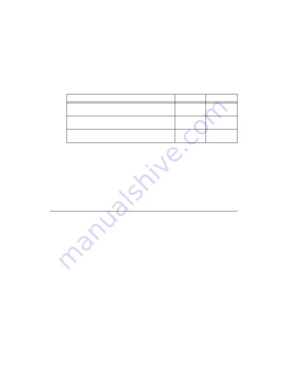
Table 1.  

Isolated Power Supply Connection Options

Connection Method

V

iso

C

iso

Digital I/O connector

10, 25

14, 26, 29, 33, 

36, 39, 42

44-pin D-SUB to 37-pin DIN rail terminal block 
(part number 778790-01 or 778791-01)

17, 33

12, 16, 28, 

32, 34

44-pin D-SUB to 37-pin NI Vision I/O Terminal Block 
and Prototyping Accessory (part number 779166-01)

V

iso

 terminal

C

iso

 terminal

Summary of Contents for NI EVS-1464RT

Page 1: ...1464RT kit the following components are necessary to set up and configure the NI EVS 1464RT One of the following power supply options Caution Use the NI EVS 1464RT only with a 24 VDC UL listed limite...

Page 2: ...t ni com or call the National Instruments office nearest you for more specific information about these products Safety Information The following section contains important safety information that you...

Page 3: ...ses overvoltage from the circuit to which they are connected during measurement or test Measurement categories establish standard impulse withstand voltage levels that commonly occur in electrical dis...

Page 4: ...radio communications services or other nearby electronics which can be determined by turning the hardware off and on you are encouraged to try to correct the interference by one or more of the follow...

Page 5: ...in or unplugging any connector Ground the unit to minimize the possibility of static electricity damage Refer to Figure 1 while completing the following steps to install the NI EVS 1464RT Figure 1 NI...

Page 6: ...ion Cameras Connect the camera Ethernet cable to the secondary network connector on the NI EVS 1464RT front panel The camera is now attached to the NI EVS 1464RT Connecting the Power Supply To connect...

Page 7: ...power supply cord into an outlet The orange ISO LED on the NI EVS 1464RT front panel will illuminate when the computer is on and an isolated power supply is properly connected Configuring the Developm...

Page 8: ...T To use MAX to configure the NI EVS 1464RT complete the instructions in the Configuring the NI EVS 1464RT with MAX section of this document Installing NI Vision Acquisition Software The latest versio...

Page 9: ...4RT The NI EVS 1464RT automatically attempts to detect the presence of a network If a DHCP server is not available the NI EVS 1464RT uses a link local address to connect directly to the development co...

Page 10: ...ied to it The NI EVS 1464RT is now connected to the development computer through a network Configuring the NI EVS 1464RT for Deployment The following sections describe how to use the application devel...

Page 11: ...t the NI EVS 1464RT with a MAC address that corresponds to the MAC address on the bottom label of the NI EVS 1464RT you want to configure Refer to Appendix D Common Questions of the NI EVS 1464 Series...

Page 12: ...Vision Builder AI RT Images directory where Vision Builder AI is the location where Vision Builder AI is installed 4 Click OK to apply the IP configuration settings and download software to the NI EVS...

Page 13: ...l Programs National Instruments Measurement Automation 2 Expand the Remote Systems branch of the configuration tree and select the device you want to configure Refer to Appendix D Common Questions of...

Page 14: ...ttings to open the Advanced Ethernet Settings dialog box 4 Select the MAC address for the secondary Ethernet connector from the Ethernet Devices list 5 Select TCP IP Network in the Mode list 6 Manuall...

Page 15: ...464RT systems are intended for indoor use only Maximum altitude 2 000 m Pollution Degree IEC 60664 2 Operating Environment Ambient temperature range 0 C to 45 C IEC 60068 2 1 and IEC 60068 2 2 Relativ...

Page 16: ...ctive safety 2004 108 EC Electromagnetic Compatibility Directive EMC Online Product Certification Refer to the product Declaration of Conformity DoC for additional regulatory compliance information To...

Page 17: ...I Documentation You can also access context help within Vision Builder AI by clicking the Show Context Help button on the Vision Builder AI toolbar Examples of common Vision Builder AI inspections are...

Page 18: ...calibration certificate for your product at ni com calibration National Instruments corporate headquarters is located at 11500 North Mopac Expressway Austin Texas 78759 3504 National Instruments also...

Page 19: ...ther product and company names mentioned herein are trademarks or trade names of their respective companies For patents covering National Instruments products technology refer to the appropriate locat...

Reviews: