background image

Complete the following steps to reset the CMOS and reset the BIOS settings to factory default
values.
1.

Disconnect power from the cRIO-9036.

2.

Press the CMOS reset button and hold it for 1 second.

3.

Reconnect power to the cRIO-9036.

The 

BIOS Reset Detected

 warning message appears onscreen.

Note


If the CMOS battery is dead, the CMOS reset button will not work.

Power-On Self Test Warning Messages

The cRIO-9036 POST displays warning messages for specific issues onscreen. You can use
MAX to enable Console Out to send these warning messages through the RS-232 serial port.

The POST can display the following warning messages:

BIOS Reset Detected—This warning is displayed when the CMOS Reset button has been
pushed. This warning indicates that the BIOS settings have the default values.

CMOS Battery Is Dead—This warning is displayed when the CMOS battery is dead and
must be replaced. The BIOS settings are preserved even when the CMOS battery is dead,
but the system will boot very slowly because the BIOS cannot optimize boot time by
saving specific system information to CMOS.

BIOS Setup Utility

Use the BIOS setup utility to change configuration settings and to enable special functions.
The cRIO-9036 ships with configuration settings that work for most applications, but you can
use the BIOS setup utility to change configuration settings to meet the needs of your
application.

Changing BIOS settings can cause incorrect behavior, including failure to boot. In general, do
not change a setting unless you are sure what the setting does. Reset the BIOS settings to
restoring the default configuration settings.

Launching the BIOS Setup Utility

Complete the following steps to launch the BIOS setup utility.
1.

Connect a video monitor to the Mini DisplayPort connector on the cRIO-9036.

2.

Connect a USB keyboard to one of the USB host ports on the cRIO-9036.

3.

Power on or reboot the cRIO-9036.

4.

Hold down either the <F10> key or the <Del> key until 

Please select boot

device:

 appears onscreen.

5.

Use the Down Arrow key to select 

Enter Setup

 and press <Enter>. The setup utility

loads after a short delay.

The Main setup menu is displayed when you first enter the BIOS setup utility.

BIOS Setup Utility Keyboard Navigation

Use the following keys to navigate through the BIOS setup utility:

NI cRIO-9036 User Manual

  | 

© National Instruments

  | 

33

Summary of Contents for NI cRIO-9036

Page 1: ...unting and operating the device USB 2 0 Host Port USB 2 0 Device Port 1 GB DDR3L RJ 50 RS 232 Serial Port RJ 50 RS 485 422 DTE Serial Port SD Card Slot Intel Atom E3825 1 33 GHz Dual Core System On Ch...

Page 2: ...29 Mounting the Device on a Rack 31 Mounting the Device on a Desktop 31 BIOS Configuration 32 Resetting the System CMOS and BIOS Settings 32 Power On Self Test Warning Messages 33 BIOS Setup Utility...

Page 3: ...g steps to find the cRIO 9036 on a network using DHCP 1 Disable secondary network interfaces on the host computer such as a wireless access card on a laptop 2 Ensure that any anti virus and firewall s...

Page 4: ...bottom of the window d Select Static on the Configure IPv4 Address control e Enter values for IPv4 Address Subnet Mask Gateway and DNS Server based on the information you recorded Be sure to enter a...

Page 5: ...ing on prevents any LabVIEW startup applications from running Disable FPGA Startup App Rebooting the cRIO 9036 with this setting on prevents autoloading of any FPGA application Enable Secure Shell SSH...

Page 6: ...Removable Storage 4 RS 232 Serial Port 5 RS 485 422 DTE Serial Port 6 Mini DisplayPort 7 USB Host Ports 8 USB Device Port RJ 45 Gigabit Ethernet Ports The cRIO 9036 has two tri speed RJ 45 Gigabit Eth...

Page 7: ...ossover cable to connect to a host computer The following NI Ethernet cables are available for the cRIO 9036 Table 3 RJ 45 Gigabit Ethernet Cables Cables Length Part Number CAT 5E Ethernet Cable shiel...

Page 8: ...nd V2 inputs the cRIO 9036 operates from the V1 input If the input voltage to V1 is insufficient the cRIO 9036 operates from the V2 input The cRIO 9036 has reverse voltage protection The following NI...

Page 9: ...shing or lit because file corruption may result Note Screw the slot cover closed completely Tighten the captive screws to a maximum torque of 0 75 N m 6 7 lb in using a 1 Phillips screwdriver Do not o...

Page 10: ...h Part Number RS 232 S8 Serial Cable 10 Position Modular Plug to 9 Pin DSUB 1 m 182845 01 2 m 182845 02 3 m 182845 03 RS 485 422 DTE Serial Port The cRIO 9036 has an RS 485 422 DTE serial port that is...

Page 11: ...E Serial Port Accessory Accessory Length Part Number RS 485 S8 Serial Cable 10 Position Modular Plug to 9 Pin DSUB Isolated 1 m 184428 01 Mini DisplayPort Use the Mini DisplayPort to connect a monitor...

Page 12: ...rt Accessories Accessory Length Part Number Mini DisplayPort to Full DisplayPort Native Cable 0 5 m 157232 0R5 1 m 157232 01 2 m 157232 02 Mini DisplayPort to VGA Adapter Cable 0 5 m 157230 0R5 Mini D...

Page 13: ...152166 02 Related Information File System on page 20 Installing a Ferrite on the USB Cables You must install a ferrite around all USB cables connected to the USB host ports to ensure that the cRIO 903...

Page 14: ...s Caution Do not hot swap USB devices while the cRIO 9036 is in a hazardous location or connected to high voltages If the cRIO 9036 is not in a hazardous location you can connect and disconnect USB de...

Page 15: ...to default settings 1 Hold the RESET button for 5 seconds and then release it to boot the controller in safe mode and enable Console Out 2 Hold the RESET button again for 5 seconds to boot the control...

Page 16: ...RIO 9036 provides the following LEDs Figure 5 cRIO 9036 LEDs 5 4 1 2 3 6 1 POWER LED 2 STATUS LED 3 USER1 LED 4 USER FPGA1 LED 5 Gigabit Ethernet LEDs 6 SD LEDs POWER LED Indicators The following tabl...

Page 17: ...to safe mode by pressing the reset button for longer than five seconds or by enabling safe mode in MAX Refer to the Measurement Automation Explorer MAX Help for information about safe mode Blinks four...

Page 18: ...LED to help debug your application or retrieve application status Refer to the LabVIEW Help for information about programming this LED Ethernet LED Indicators The following table lists the Ethernet LE...

Page 19: ...hile this LED is lit Chassis Grounding Screw The cRIO 9036 provides a chassis grounding screw Figure 6 cRIO 9036 Chassis Grounding Screw 1 1 Chassis Grounding Screw For EMC compliance you must connect...

Page 20: ...y is dead The cRIO 9036 still starts but the system clock is reset to the date and time of the BIOS release The battery is not user replaceable If you need to replace the CMOS battery contact NI Refer...

Page 21: ...e accessory requires tool access to the top right and bottom of the cRIO 9036 What to Use cRIO 9036 C Series modules Module Immobilization accessory kit 158533 01 Module immobilization bracket Install...

Page 22: ...x T20 driver Tighten the screw to a maximum torque of 1 3 N m 11 5 lb in 5 Install the two M3 x 0 5 flat head screws from the accessory kit in the top and bottom of the cRIO 9036 using the appropriate...

Page 23: ...5 mm DIN rail on a desktop or in a rack Mounting the cRIO 9036 in these or other configurations can reduce the maximum allowable ambient temperature and can affect the typical accuracy of modules in t...

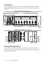
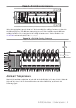
Page 24: ...226 6 mm 8 92 in 8 6 mm 0 34 in 88 1 mm 3 47 in Figure 10 cRIO 9036 Side Dimensions 53 4 mm 2 10 in 53 4 mm 2 10 in 53 4 mm 2 10 in 53 4 mm 2 10 in 44 0 mm 1 73 in 44 0 mm 1 73 in 44 0 mm 1 73 in 44...

Page 25: ...quire different cabling clearances For a complete list of cabling clearances for C Series modules visit ni com info and enter the Info Code crioconn Figure 12 cRIO 9036 Cabling Clearance 29 1 mm 1 14...

Page 26: ...e Directly on a Flat Surface For environments with high shock and vibration NI recommends mounting the cRIO 9036 directly on a flat rigid surface using the mounting holes in the cRIO 9036 What to Use...

Page 27: ...of insertion into the cRIO 9036 Tighten the screws to a maximum torque of 1 3 N m 11 5 lb in Surface Mounting Dimensions The following figure shows the surface mounting dimensions for the cRIO 9036 Fi...

Page 28: ...ounting plate to the cRIO 9036 using the screwdriver and M4 x 10 screws Tighten the screws to a maximum torque of 1 3 N m 11 5 lb in You must use the screws provided with the NI panel mounting kit bec...

Page 29: ...2 mm 0 29 in 25 4 mm 1 00 in Mounting the cRIO 9036 on a DIN Rail You can use the NI DIN rail mounting kit to mount the cRIO 9036 on a standard 35 mm DIN rail What to Use cRIO 9036 Screwdriver Philli...

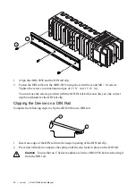
Page 30: ...y are the correct depth and thread for the DIN rail clip Clipping the Device on a DIN Rail Complete the following steps to clip the cRIO 9036 on a DIN rail 1 2 1 Insert one edge of the DIN rail into t...

Page 31: ...te You must use the NI DIN rail mounting kit 157268 01 in addition to a rack mounting kit Mounting the Device on a Desktop You can use the NI desktop mounting kit to mount the cRIO 9036 on a desktop W...

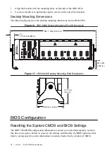
Page 32: ...sions 2 17 2 mm 0 68 in 361 7 mm 14 24 in 39 1 mm 1 54 in Figure 17 cRIO 9036 Desktop Mounting Side Dimensions 132 8 mm 5 23 in 127 2 mm 5 01 in BIOS Configuration Resetting the System CMOS and BIOS S...

Page 33: ...ation to CMOS BIOS Setup Utility Use the BIOS setup utility to change configuration settings and to enable special functions The cRIO 9036 ships with configuration settings that work for most applicat...

Page 34: ...ation information BIOS Version and Build Date These values indicate the version of the controller BIOS and the date on which the BIOS was built Embedded Firmware Version This value identifies the buil...

Page 35: ...ff the cRIO 9036 returns to the soft off power state after AC power is restored When set to Turn On the cRIO 9036 powers on when DC power is restored Power Button Off Behavior This setting specifies h...

Page 36: ...e hub descriptor Device Power Up Delay in Seconds This setting specifies the number of seconds the POST waits for a USB device or hub to power on This setting is only visible when the Device Power Up...

Page 37: ...urations to boot settings The factory default settings provide the most compatible and optimal configuration Setup Prompt Timeout This setting specifies the number of seconds the system waits for a BI...

Page 38: ...to select this option Save Changes Changes made to BIOS settings during this session are committed to NVRAM The setup utility remains active allowing further changes Discard Changes Any changes made...

Page 39: ...r s declaration of conformity This system affords the user protection for electromagnetic compatibility EMC and product safety You can obtain the DoC for your product by visiting ni com certification...

Page 40: ...s EULAs and third party legal notices in the readme file for your NI product Refer to the Export Compliance Information at ni com legal export compliance for the NI global trade compliance policy and...

Reviews: