


5-22
|
ni.com
Chapter 5
Counters
After the counter has been armed and an active edge occurs on the Aux input, the counter counts
the number of rising (or falling) edges on the Source. The counter ignores additional edges on
the Aux input.
The counter stops counting upon receiving an active edge on the Gate input. The counter stores
the count in the FIFO.
You can configure the rising or falling edge of the Aux input to be the active edge. You can
configure the rising or falling edge of the Gate input to be the active edge.
Use this type of measurement to count events or measure the time that occurs between edges on
two signals. This type of measurement is sometimes referred to as start/stop trigger
measurement, second gate measurement, or A-to-B measurement.
Refer to the following sections for more information about the cDAQ chassis edge-separation
measurement options:
•
Single Two-Signal Edge-Separation Measurement
•
Implicit Buffered Two-Signal Edge-Separation Measurement
•
Sample Clocked Buffered Two-Signal Separation Measurement
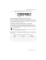
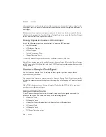
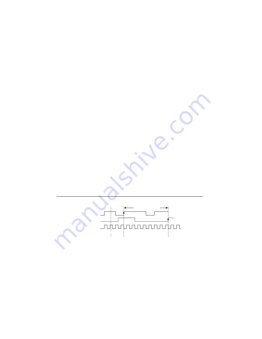
Single Two-Signal Edge-Separation Measurement
With single two-signal edge-separation measurement, the counter counts the number of rising
(or falling) edges on the Source input occurring between an active edge of the Gate signal and
an active edge of the Aux signal. The counter then stores the count in the FIFO and ignores other
edges on its inputs. Software then reads the stored count.
Figure 5-23 shows an example of a single two-signal edge-separation measurement.
Figure 5-23.
Single Two-Signal Edge-Separation Measurement
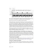
Implicit Buffered Two-Signal Edge-Separation Measurement
Implicit buffered and single two-signal edge-separation measurements are similar, but implicit
buffered measurement measures multiple intervals.
The counter counts the number of rising (or falling) edges on the Source input occurring between
an active edge of the Gate signal and an active edge of the Aux signal. The counter then stores
AUX
Co
u
nter
Armed
8
0
0
0
1
2
3
4
5
6
7
8
8
0
8
Me
asu
red Interv
a
l
GATE
S
OURCE
Co
u
nter V
a
l
u
e
L
a
tched V
a
l
u
e


