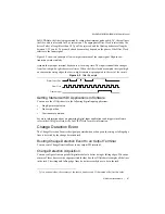
© National Instruments
|
3-3
NI cDAQ-9181/9184/9188/9191 User Manual
Analog Output Triggering Signals
Analog output supports two different triggering actions: AO Start Trigger and AO Pause
Trigger.
An analog or digital trigger can initiate these actions. Up to two C Series parallel digital input
modules can be used in any chassis slot to supply a digital trigger. An analog trigger can be
supplied by some C Series analog modules.
sections for more information
about the analog output trigger signals.
Analog Output Timing Signals
The cDAQ chassis features the following AO (waveform generation) timing signals:
•
•
AO Sample Clock Timebase Signal
•
•
Signals with an * support digital filtering. Refer to the
section of Chapter 4,
, for more information.
AO Sample Clock Signal
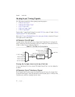
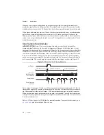
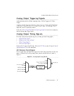
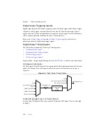
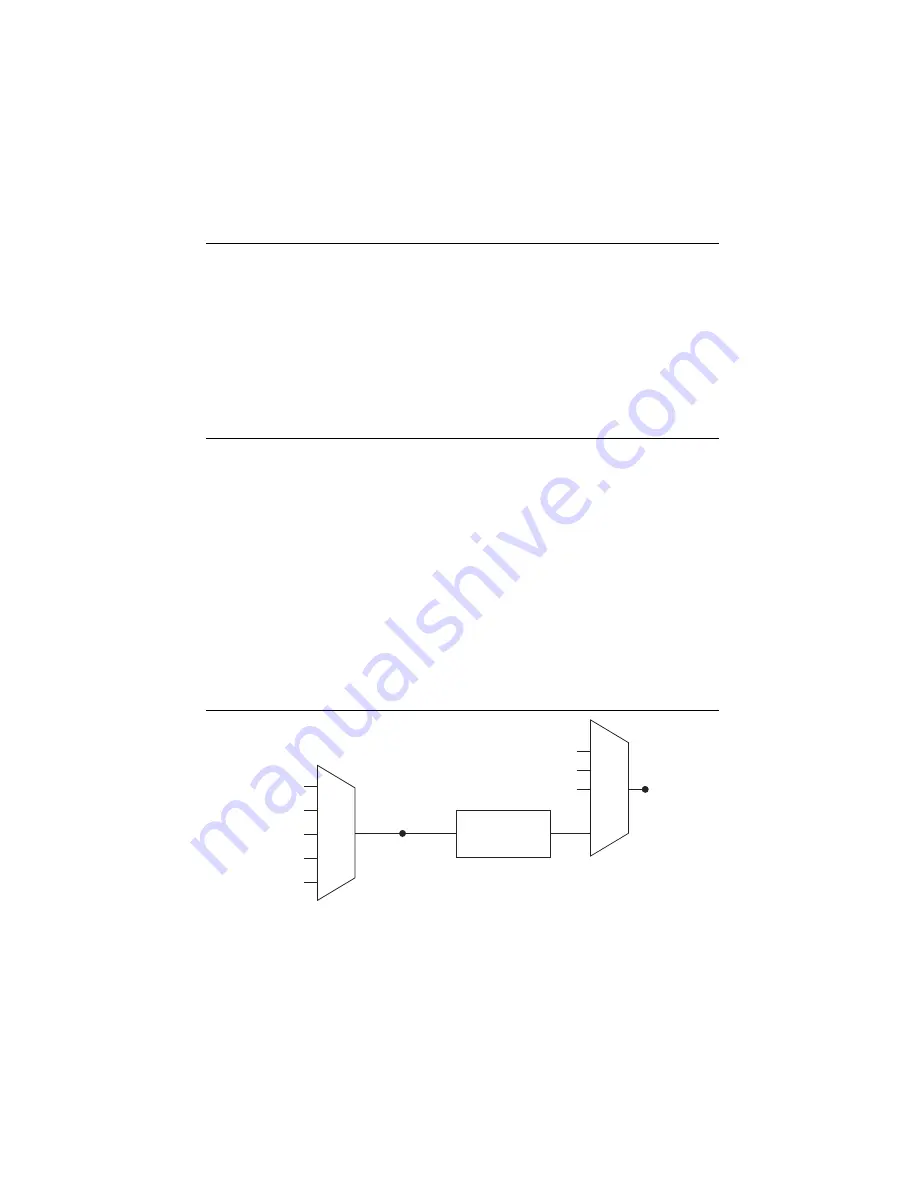
The AO sample clock (ao/SampleClock) signals when all the analog output channels in the task
update. AO Sample Clock can be generated from external or internal sources as shown in
Figure 3-1.
Figure 3-1.
Analog Output Timing Options
Programmable
Clock
Divider
AO Sample Clock
Timebase
PFI
Analog Comparison Event
Ctr
n Internal Output
AO Sample Clock
Analog Comparison
Event
20 MHz Timebase
80 MHz Timebase
PFI
100 kHz Timebase

