20
|
ni.com
|
NI 9502 Operating Instructions and Specifications
–
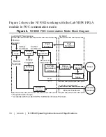
Install a snap-on ferrite bead from Table 1 on the power
supply cable (marked as Ferrite 2 in Figure ) and the motor
cable (marked as Ferrite 3 in Figure ) as close to the
NI 9502 as practical. If a single, shielded cable is used,
install only one ferrite bead (marked as Ferrite 2 in Figure )
as shown. If two cables are used, install two ferrites from
Table 1 as shown in Figure . The ferrite beads should
encompass the entire cable, including the cable shield.
Select the ferrite with the smallest aperture that will fit the
actual cable(s) used.
–
Ferrite beads can be ordered from the National Instruments
Web site at
ni.com
by selecting
Order by Part Number
.
Power to the module must be off when adding ferrites.
Table 1.
Ferrite Sizing Chart for Power Supply and Motor Side Cables
NI Part Number
Aperture Size mm (inches)
781233-01
7.0 (0.275)
781233-02
10.2 (0.402)
777297-01
13.4 (0.528)

