background image

NI 9502 Operating Instructions and Specifications

|

© National Instruments

|

15

Help

, available by selecting 

Help»LabVIEW Help

, for 

information about determining the proper Hall input connections 
to the NI 9502 module when using the NI 9502 module in 
trapezoidal commutation mode.

Note

The LabVIEW SoftMotion Module provides an 

example that allows you to automatically determine the 
phasing for FOC commutation mode.

LED Indicators

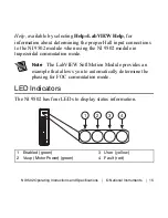
The NI 9502 has four LEDs to display status information.

1

Enabled (green)

2

Vsup (Motor Power) (green)

3

User (yellow)

4

Fault (red)

1

2

3

4

Summary of Contents for NI 9502

Page 1: ...OPERATING INSTRUCTIONS AND SPECIFICATIONS NI 9502 Brushless Servo Motor Drive ni com manuals Deutsch Français ...

Page 2: ...in assignments for the NI 9502 Note The safety guidelines and specifications in this document are specific to the NI 9502 The other components in the system may not meet the same safety ratings and specifications Refer to the documentation for each component in the system to determine the safety ratings and specifications for the entire system Related Information ...

Page 3: ...C T4 hazardous locations and nonhazardous locations only Follow these guidelines if you are installing the NI 9502 in a potentially explosive environment Not following these guidelines may result in serious injury or death Caution Do not disconnect I O side wires or connectors unless power has been switched off or the area is known to be nonhazardous Caution Do not remove modules unless power has ...

Page 4: ... Special Conditions for Hazardous Locations Use in Europe and Internationally This equipment has been evaluated as Ex nA IIC T4 Gc equipment under DEMKO Certificate No 07 ATEX 0626664X and is IECEx UL 14 0089X certified Each module is marked II 3G and is suitable for use in Zone 2 hazardous locations in ambient temperatures of 40 C Ta 70 C If you are using the NI 9502 in Gas Group IIC hazardous lo...

Page 5: ...netic Compatibility Guidelines This product was tested and complies with the regulatory requirements and limits for electromagnetic compatibility EMC as stated in the product specifications These requirements and limits are designed to provide reasonable protection against harmful interference when the product is operated in its intended operational electromagnetic environment This product is inte...

Page 6: ...by National Instruments could void your authority to operate it under your local regulatory rules Caution The inputs outputs of this product can be damaged if subjected to Electrostatic Discharge ESD To prevent damage industry standard ESD prevention measures must be employed during installation maintenance and operation Caution To ensure compliance with the applicable regulatory requirements prod...

Page 7: ...oduct visit ni com certification and search for the LR certificate or look for the Lloyd s Register mark on the product label Caution In order to meet the EMC requirements for marine applications install the product in a shielded enclosure with shielded and or filtered power and input output ports In addition take precautions when designing selecting and installing measurement probes and cables to...

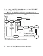
Page 8: ...IEW FPGA module Refer to the NI 9502 topic in the LabVIEW Help available by selecting Help LabVIEW Help for more information about the available status information Depending on software settings the NI 9502 can operate in either Trapezoidal or Field Oriented Control FOC commutation mode Refer to the NI 9502 topic in the LabVIEW Help available by selecting Help LabVIEW Help for more information abo...

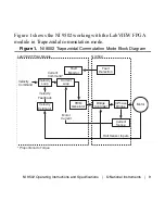
Page 9: ...commutation mode Figure 1 NI 9502 Trapezoidal Commutation Mode Block Diagram Velocity Loop Current Loop Fault Monitor Bridge Controller Fault Detection Current Sense Motor Velocity Command Current Command LabVIEW FPGA Module NI 9502 Motor Current Velocity Feedback Velocity Estimator Proportional to Torque PWM Generator Hall Sensor Inputs 3 Phase Bridge ...

Page 10: ... Algorithm Fault Monitor Bridge Controller Fault Detection Current Sense Encoder Feedback Motor Velocity Command Current Command Position Setpoint LabVIEW FPGA Module NI 9502 Encoder Feedback Position Decoder Phase U W Current Velocity Feedback Position Feedback Velocity Estimator Proportional to Torque Available with the LabVIEW NI SoftMotion Module Premium SVPWM Generators 3 Total Hall Inputs C ...

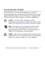
Page 11: ...ignments Caution To ensure EMC compliance special considerations are required for all cable connections Refer to the Cable Requirements for EMC Compliance section Note You must use 2 wire ferrules to create a secure connection when connecting more than one wire to a single terminal on the NI 9502 screw terminal Refer to Figure 4 for an illustration of using ferrules Caution Do not turn on or plug ...

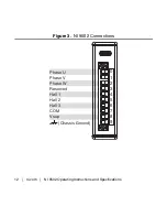
Page 12: ...12 ni com NI 9502 Operating Instructions and Specifications Figure 3 NI 9502 Connections Phase U Phase V Phase W Reserved Hall 1 Hall 2 Hall 3 COM Vsup Chassis Ground 0 1 2 3 4 5 6 7 8 9 ...

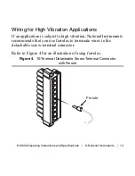
Page 13: ...ications If an application is subject to high vibration National Instruments recommends that you use ferrules to terminate wires to the detachable screw terminal connector Refer to Figure 4 for an illustration of using ferrules Figure 4 10 Terminal Detachable Screw Terminal Connector with Ferrule Ferrule ...

Page 14: ... multiconductor cable with an overall shield and conductors of 12 to 20 AWG for the motor cable Figure in the Cable Requirements for EMC Compliance section shows a simplified connection diagram Hall Effect Sensor Connections Use the Hall 1 Hall 2 and Hall 3 inputs to connect the motor Hall effect sensors For proper phase switching to occur the Hall sensors from the motor must be connected to the c...

Page 15: ... connections to the NI 9502 module when using the NI 9502 module in trapezoidal commutation mode Note The LabVIEW SoftMotion Module provides an example that allows you to automatically determine the phasing for FOC commutation mode LED Indicators The NI 9502 has four LEDs to display status information 1 Enabled green 2 Vsup Motor Power green 3 User yellow 4 Fault red 1 2 3 4 ...

Page 16: ...abVIEW Help for information about enabling the drive Vsup The Vsup LED green illuminates when the motor DC power supply is properly connected User You can define the User LED yellow to meet the needs of your application Use the User LED I O node to turn this LED on and off Refer to the NI 9502 topic in the LabVIEW Help available by selecting Help LabVIEW Help for information about the NI 9502 User...

Page 17: ... topic in the LabVIEW Help available by selecting Help LabVIEW Help for more information about this fault Caution Vsup greater than 40 V will result in damage to the NI 9502 Vsup overvoltage Caution Current greater than 8 A will result in damage to the NI 9502 Overcurrent Module current sampling fault Refer to the NI 9502 Module Faults topic in the LabVIEW Help available by selecting Help LabVIEW ...

Page 18: ...hile it is enabled the power to the motor is removed and the motor decelerates to a stop based on its own friction Sleep Mode This module supports a low power sleep mode Support for sleep mode at the system level depends on the chassis that the module is plugged into Refer to the chassis manual for information about support for sleep mode If the chassis supports sleep mode refer to the software he...

Page 19: ...02 to a motor and a power supply Terminate the motor and power supply cable shields to the COM terminal of the NI 9502 In addition terminate the cable shields at the other end to either earth ground or the chassis of the connected motor and or power supply Install snap on ferrite beads to the cables as follows Install a snap on ferrite bead from Table 2 on each phase wire of the motor cable within...

Page 20: ...les are used install two ferrites from Table 1 as shown in Figure The ferrite beads should encompass the entire cable including the cable shield Select the ferrite with the smallest aperture that will fit the actual cable s used Ferrite beads can be ordered from the National Instruments Web site at ni com by selecting Order by Part Number Power to the module must be off when adding ferrites Table ...

Page 21: ... Table 2 Ferrite Sizing Chart for Module Side Motor Phase Cables NI Part Number Aperture Size mm inches 781233 02 10 2 0 402 781950 01 5 10 0 201 Motor DC Power Supply Phase U Phase V Phase W Hall 1 Hall 2 Hall 3 COM Vsup NI 9502 Shield Ferrites Refer to Tables 1 and 2 for sizing information Motor Ferrite 1 3 Total Ferrite 2 ...

Page 22: ...fications Figure 6 NI 9502 Cable Connection Two Cable Option Motor DC Power Supply Phase U Phase V Phase W Hall 1 Hall 2 Hall 3 COM Vsup NI 9502 Shield Ferrites Refer to Tables 1 and 2 for sizing information Motor Ferrite 1 3 Total Ferrite 2 Ferrite 3 ...

Page 23: ...dal commutation mode and 10 kHz for FOC commutation mode unless otherwise noted All voltages are relative to COM unless otherwise noted Input Output Characteristics Motor outputs Current 4 A 2 8 Arms continuous 8 A 5 6 Arms peak Maximum peak time 1 second Minimum dwell time between peaks 15 seconds Peak output power 0 2 kW Continuous output power 0 1 kW Commutation Field Oriented Control or Trapez...

Page 24: ...ed PWM Minimum inductance 250 µH PWM ripple frequency 20 kHz1 Current loop1 ADC resolution 12 bits Current range 8 A Sampling rate 10 kHz 100 µs Bandwidth 2 5 kHz with specified minimum inductance varies with tuning and load Hall inputs Digital logic levels Voltage 0 25 to 5 25 V High VIH 2 4 V min Low VIL 0 8 V max 1 Specifications based on the installed examples ...

Page 25: ...p capacitance 750 µF MTBF Contact NI for Bellcore MTBF specifications Drive Protection Undervoltage 6 V Caution Vsup greater than 40 V will result in damage to the module Overvoltage 32 V Power Requirements Power consumption from chassis Active mode 700 mW max Sleep mode 2 5 mW max Thermal dissipation at 70 C Active mode 1 5 W max Sleep mode 2 5 mW max ...

Page 26: ...C Series module and connectors visit ni com dimensions and search by module number Screw terminal wiring Gauge 0 2 mm2 to 2 5 mm2 26 to 14 AWG copper conductor wire with 10 mm 0 39 in of insulation stripped from the end Temperature rating 90 C Torque for screw terminals 0 5 to 0 6 N m 4 4 to 5 3 lb in Wires per screw terminal One wire per screw terminal two when using 2 wire ferrule Ferrules 0 25 ...

Page 27: ...its Channel to COM 0 to 30 VDC max Measurement Category I Isolation Channel to channel None Channel to earth ground Continuous 60 VDC Measurement Category I Withstand 1000 Vrms verified by a 5 s dielectric withstand test Measurement Category I is for measurements performed on circuits not directly connected to the electrical distribution system referred to as MAINS voltage MAINS is a hazardous liv...

Page 28: ...d energy parts of equipment circuits powered by regulated low voltage sources and electronics Caution Do not connect the NI 9502 to signals or use for measurements within Measurement Categories II III or IV Hazardous Locations U S UL Class I Division 2 Groups A B C D T4 Class I Zone 2 AEx nA IIC T4 Canada C UL Class I Division 2 Groups A B C D T4 Class I Zone 2 Ex nA IIC T4 Europe DEMKO Ex nA IIC ...

Page 29: ...designed to meet the requirements of the following standards of safety for electrical equipment for measurement control and laboratory use IEC 61010 1 EN 61010 1 UL 61010 1 CSA 61010 1 EN 60079 0 2012 EN 60079 15 2010 IEC 60079 0 Ed 6 IEC 60079 15 Ed 4 UL 60079 0 Ed 5 UL 60079 15 Ed 3 CSA 60079 0 2011 CSA 60079 15 2012 Note For UL and other safety certifications refer to the product label or the O...

Page 30: ...d laboratory use EN 61326 1 IEC 61326 1 Class A emissions Industrial immunity EN 55011 CISPR 11 Group 1 Class A emissions AS NZS CISPR 11 Group 1 Class A emissions FCC 47 CFR Part 15B Class A emissions ICES 001 Class A emissions Note For the standards applied to assess the EMC of this product refer to the Online Product Certification section Note For EMC compliance operate this device with shielde...

Page 31: ... 2014 30 EU Electromagnetic Compatibility Directive EMC 94 9 EC Potentially Explosive Atmospheres ATEX Online Product Certification Refer to the product Declaration of Conformity DoC for additional regulatory compliance information To obtain product certifications and the DoC for this product visit ni com certification search by module number or product line and click the appropriate link in the C...

Page 32: ...68 2 64 5 grms 10 to 500 Hz Sinusoidal IEC 60068 2 6 5 g 10 to 500 Hz Operating shock IEC 60068 2 27 30 g 11 ms half sine 50 g 3 ms half sine 18 shocks at 6 orientations Environmental Refer to the manual for the chassis you are using for more information about meeting these specifications Operating temperature IEC 60068 2 1 IEC 60068 2 2 40 to 70 C Storage temperature IEC 60068 2 1 IEC 60068 2 2 4...

Page 33: ...mitted to designing and manufacturing products in an environmentally responsible manner NI recognizes that eliminating certain hazardous substances from our products is beneficial to the environment and to NI customers For additional environmental information refer to the Minimize Our Environmental Impact web page at ni com environment This page contains the environmental regulations and directive...

Page 34: ...re information about WEEE recycling centers National Instruments WEEE initiatives and compliance with WEEE Directive 2002 96 EC on Waste and Electronic Equipment visit ni com environment weee ᄤֵᙃѻક ᶧ ࠊㅵ ࡲ Ё RoHS Ё ᅶ National Instruments ヺড়Ё ᄤֵᙃ ѻકЁ䰤ࠊՓ ᶤѯ ᆇ 䋼ᣛҸ RoHS DŽ Ѣ National Instruments Ё RoHS ড়㾘ᗻֵᙃˈ䇋ⱏᔩ ni com environment rohs_chinaDŽ For information about China RoHS compliance go to ni com envi...

Page 35: ...declaration of conformity This system affords the user protection for electromagnetic compatibility EMC and product safety You can obtain the DoC for your product by visiting ni com certification If your product supports calibration you can obtain the calibration certificate for your product at ni com calibration National Instruments corporate headquarters is located at 11500 North Mopac Expresswa...

Page 36: ...dme file for your NI product Refer to the Export Compliance Information at ni com legal export compliance for the National Instruments global trade compliance policy and how to obtain relevant HTS codes ECCNs and other import export data NI MAKES NO EXPRESS OR IMPLIED WARRANTIES AS TO THE ACCURACY OF THE INFORMATION CONTAINED HEREIN AND SHALL NOT BE LIABLE FOR ANY ERRORS U S Government Customers T...

Reviews: