background image

Chapter 5 

S Mode Functions 


© National Instruments Corp. 

5-31 

GPIB-232CT User Manual 

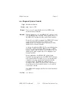
rd - Read Data * 


Type:

 I/O 

function 


Syntax:


rd

 #count [addr]

<CR> 


 Purpose:

 You 

use 

rd

 to read data from the GPIB. 


Remarks:

 The 

argument 

#count

 is a numeric string preceded by a 

number sign (

#

).  

#count

 specifies the number of bytes to 

read.  

count

 must not contain a comma.  It can specify a 

number between 1 and 65535.   


The argument 

addr

 is a device address that specifies the 

address of the device to be addressed as a Talker.  

addr


consists of a primary address and a secondary address.  The 
secondary address is separated from the primary address by a 
plus sign (

+

). 


Only the lower five bits of each address are significant.  These 
bits can be in the range from 0 through 30 for both the 
primary and the secondary address.  Therefore, the binary 
value 01100010 (decimal 98) is interpreted as decimal 2.   


The following examples all specify a primary address of 0 and 
a secondary address of 2.  The listen address is 32, the talk 
address is 64, and the secondary address is 2 or 98, which are 
equivalent.  


0+2

 or 

0+98

 or 

32+98

 or 

0+\x62


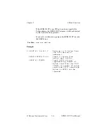
The GPIB-232CT reads data from the GPIB until the specified 
byte count is reached, the GPIB END message is received 
with a data byte, the EOS byte is received, or a timeout 
occurs.   


Because you may not know for certain the number of bytes 
actually read from the GPIB, the GPIB-232CT returns the 
received GPIB data to you in the following manner.  First, the 
GPIB-232CT returns to you all bytes it read from the GPIB.  
Next, it sends null bytes until the total number of bytes 
returned to you matches your requested count.  Finally, it 
returns a numeric string representing the number of bytes that 
it actually read from the GPIB. 

Summary of Contents for GPIB-232CT

Page 1: ...rutilized and idle equipment along with credit for buybacks and trade ins Custom engineering so your equipment works exactly as you specify Critical and expedited services Leasing Rentals Demos In sto...

Page 2: ...Copyright 1988 1992 National Instruments Corporation All Rights Reserved GPIB 232CT User Manual MicroGPIB RS 232 to IEEE 488 Controller July 1992 Edition Part Number 320114 01...

Page 3: ...anada Technical support fax 512 794 5678 Branch Offices Australia 03 879 9422 Belgium 02 757 00 20 Canada 519 622 9310 Denmark 45 76 73 22 France 1 48 65 33 70 Germany 089 714 5093 Italy 02 48301892 J...

Page 4: ...carefully reviewed for technical accuracy In the event that technical or typographical errors exist National Instruments reserves the right to make changes to subsequent editions of this document with...

Page 5: ...s owner s modification of the product owner s abuse misuse or negligent acts and power failure or surges fire flood accident actions of third parties or other events outside reasonable control Copyrig...

Page 6: ...stallation However the chances of interference are much less if the equipment is used according to this instruction manual If the equipment does cause interference to radio or television reception whi...

Page 7: ...tal and physical specifications Chapter 2 The GPIB 232CT Modes of Operation explains the two modes of operation of the GPIB 232CT Chapter 3 Installation and Configuration in S Mode contains the S mode...

Page 8: ...rise Appendix F Parallel Polling explains the use and operation of Parallel Polls Appendix G Setting Switches gives additional details about setting switches on the GPIB 232CT Appendix H Sample Progra...

Page 9: ...reviations are units of measure that are used in the text of this manual A ampere C Celsius degree greater than greater than or equal to hex hexadecimal Hz hertz in inch K 1 024 kbytes sec 1000 bytes...

Page 10: ...ems you can use the following toll free number between the hours of 8 00 a m and 5 30 p m central time to reach the National Instruments applications engineering department 512 794 0100 800 IEEE 488 t...

Page 11: ...G Mode 2 1 Chapter 3 Installation and Configuration in S Mode 3 1 Installation 3 1 Step 1 Inspection 3 1 Step 2 Verify the Voltage Requirement 3 2 Step 3 Configure the Operating Parameters 3 2 Set Con...

Page 12: ...s Received from Serial Port 5 11 eos Change Disable GPIB EOS Termination Mode 5 12 eot Enable Disable END Message on GPIB Writes 5 15 gts Go from Active Controller to Standby 5 17 ibcl Enter ibcl Oper...

Page 13: ...gramming Message 7 1 How Messages are Processed 7 2 Function Names 7 2 Function Argument Delimiters 7 2 Abbreviation for Argument 7 2 Status Information 7 3 Communicating with the GPIB 232CT and the S...

Page 14: ...10 srqen Enable Disable Setting of SRQ 8 12 stat Return GPIB 232CT Status 8 14 xon Change Serial Port XON XOFF Protocol 8 20 Appendix A Multiline Interface Messages A 1 Multiline Interface Messages A...

Page 15: ...fy D 6 Physical and Electrical Characteristics D 6 Configuration Restrictions D 9 Related Document D 9 Appendix E Common Questions E 1 S Mode E 1 G Mode E 3 Appendix F Parallel Polling F 1 Operation F...

Page 16: ...t Function H 9 Step 2 Serial Port Functions H 9 Step 3 GPIB Initialization Functions H 9 Step 4 Communicate with rd and wrt Functions H 9 G Mode Sample Programs H 10 Using an HP 7475A Plotter with a G...

Page 17: ...e Configuration C 4 Figure C 3 Null Modem Cable Configuration C 5 Figure C 4 Minimum Null Modem Cable Configuration C 6 Figure D 1 GPIB Cable Connector D 4 Figure D 2 Linear Configuration of the GPIB...

Page 18: ...4 9 Table 4 9 Serial Port Initialization Functions 4 10 Table 4 10 General Use Functions 4 10 Table 4 11 GPIB 232CT Functions 4 11 Table 5 1 Data Transfer Termination Methods 5 12 Table 5 2 GPIB Stat...

Page 19: ...Contents National Instruments Corp xix GPIB 232CT User Manual Table C 1 RS 232 Serial Port Pinouts C 2...

Page 20: ...ng and listening on the GPIB The GPIB 232CT is also capable of interfacing RS 232 instruments and peripherals to the GPIB The GPIB 232CT has all the software and logic required to implement the physic...

Page 21: ...ur kit should contain the following components Component Part Number One of the following boxes GPIB 232CT 64K RAM 115 VAC 776173 01 GPIB 232CT 256K RAM 115 VAC 776173 02 GPIB 232CT 64K RAM 230 VAC 77...

Page 22: ...nt Component Part Number Rackmount Kit Single 1 unit 180480 01 Dual 2 units 180480 02 RS 232 Shielded Cables Compatible with IBM PC DTE to DTE 2 m 180459 02 DTE to DTE 4 m 181459 04 Double Shielded GP...

Page 23: ...1 1 Electrical Characteristics Characteristic Specification Power Supply Unit Wall mount type 115 VAC or 230 VAC 50 60 Hz input 9 VDC 1A max output Voltage 9 VDC unregulated Current 640 mA typical 1...

Page 24: ...7 in by 8 4 in 40 6 mm by 144 8 mm by 213 4 mm Case Material All metal enclosure Rack Mounting Single or dual kits available Weight 28 oz without power supply unit The GPIB 232CT Front Panel The front...

Page 25: ...een applied and the ON OFF switch is in the ON position READY Indicates that the power on self test has passed successfully and the unit is ready to operate TALK Indicates that the GPIB 232CT is confi...

Page 26: ...ents Corp 1 7 GPIB 232CT User Manual The GPIB 232CT Rear Panel The rear panel of the GPIB 232CT is shown in Figure 1 3 The power cable RS 232 cable and GPIB cable are shown connected to the rear panel...

Page 27: ...lock assemblies The RS 232 connector will accept standard 25 pin D subminiature male connectors A diagram of the serial connector and the signals supported is shown in Figure 1 4 For more information...

Page 28: ...IB connector and the signals supported is shown in Figure 1 5 a suffix indicates that the signal is active low DIO1 DIO2 DIO3 DIO4 EOI DAV NRFD NDAC IFC SRQ ATN SHIELD DIO5 DIO6 DIO7 DIO8 REN GND TW P...

Page 29: ...nd a GPIB device The GPIB 232CT s mode of operation is determined by the role the serial device plays in your setup Is the serial device a Controller Is it going to manage the GPIB address devices and...

Page 30: ...re the GPIB 232CT enables a serial printer to be programmed from a GPIB Controller Figure 2 2 A Serial Printer Connected to a GPIB Controller Now turn to Chapter 3 for S mode installation and configur...

Page 31: ...been caused in shipment 2 Verify the voltage requirement 3 Configure the operating parameters 4 Connect the cables 5 Power on the unit These steps are described in more detail in the following section...

Page 32: ...rameters you must open the unit and set the configuration switches To change the configuration switches follow these steps 1 Disconnect power to the unit and disconnect any cables that may be connecte...

Page 33: ...the ON side OFF indicates that the switch is pressed on the OFF side Figure 3 1 S Mode Switch Settings Tables 3 1 and 3 2 show the possible configurations of the eight switches and what the configurat...

Page 34: ...igure 3 2 shows the GPIB 232CT s factory default setting for switch U22 Switch 1 is OFF this indicates that the GPIB 232CT will be operating in S mode Switch 2 is OFF this indicates that the GPIB 232C...

Page 35: ...system Be sure to obey all IEEE 488 cabling restrictions and use only double shielded GPIB cable 3 Connect the power jack of the wall mount power supply to the power receptacle on the back panel of t...

Page 36: ...rmat A programming message consists of a function name one or more arguments optional followed by a carriage return CR a linefeed LF or a carriage return followed by a linefeed CR LF You can enter pro...

Page 37: ...programming message on a line by line basis The GPIB 232CT buffers the entire message interprets the function name and arguments then executes the message The data portions of the wrt and cmd function...

Page 38: ...use abbreviations for some arguments They are as follows addr a GPIB address alist one or more addrs bool a boolean value 1 true on or enable 0 false off or disable GPIB Address Each device on the GP...

Page 39: ...with a backslash x x or backslash X X Each of the following numeric strings represents the decimal integer value 112 112 160 x70 The GPIB address argument described in the preceding discussion GPIB A...

Page 40: ...e two methods permit a Talker to send data messages of any length without the Listener s knowing in advance the number of bytes in the transmission END message The Talker asserts the EOI End Or Identi...

Page 41: ...Characteristics Power on Characteristic Value Function Echo bytes to serial port no echo Ignore serial port errors yes spign Send XON XOFF no xon Recognize XON XOFF no xon Table 4 2 GPIB Characteristi...

Page 42: ...ns are divided into subgroups as shown in the following tables The subgroups are listed with the most frequently used groups first Often the I O and bus management functions are the only ones you need...

Page 43: ...e or disable GPIB end of string termination mode EOT on off Enable or disable END termination message on GPIB write operations ONL on off Place the GPIB 232CT online offline RSC on off Request System...

Page 44: ...ds commands GTS mode Go from Active Controller to Standby PCT address Pass Control SIC time Send interface clear SRE on off Set clear remote enable Table 4 8 Parallel Poll Functions Function Purpose I...

Page 45: ...unction Purpose ECHO on off Echo characters received from serial port SPIGN on off Ignore serial port errors XON modes Change serial port XON XOFF protocol General Use Functions Table 4 10 General Use...

Page 46: ...cified device s CMD count commands Send IEEE 488 commands ECHO on off Echo characters received from serial port EOS modes eoschar Change or disable GPIB end of string termination mode EOT on off Enabl...

Page 47: ...Poll RSC on off Request System Control RSP address list Conduct request a serial poll RSV status byte Request service and or set or change the serial poll status byte SIC time Send interface clear SPI...

Page 48: ...carriage return CR a linefeed LF or a carriage return followed by a linefeed CR LF The terminator is denoted by a CR in the syntax portions of the function descriptions In the programming examples the...

Page 49: ...your needs In the descriptions that follow these functions are marked with an asterisk These are the most frequently used functions It is only necessary for you to send enough characters of the functi...

Page 50: ...l asynchronously If the argument bool is 1 the GPIB 232CT takes control after any handshake that is in progress completes that is it takes control synchronously If you call cac without an argument the...

Page 51: ...of each address are significant These bits can be in the range from 0 through 30 for both the primary and the secondary address Therefore the binary value 01100010 decimal 98 is interpreted as decimal...

Page 52: ...User Manual Examples 1 PRINT 1 caddr 0 22 Give GPIB 232CT a primary address of 0 and a secondary address of 22 2 PRINT 1 CADDR 1 Change GPIB 232CT primary address to 1 and disable secondary addressing...

Page 53: ...arated from the primary address by a plus sign Only the lower five bits of each address are significant These bits can be in the range from 0 through 30 for both the primary and the secondary address...

Page 54: ...ssed back to you or you must send IFC to make yourself CIC before making this call Otherwise the ECIC error will be posted See Also Appendix D for more information on clearing devices and Appendix B f...

Page 55: ...linefeed LF that you include to indicate the end of the programming message The argument commands is a list of GPIB commands These commands are represented by their ASCII character equivalents For ex...

Page 56: ...the GPIB 232CT After cmd terminates the GPIB 232CT records the number of command bytes it actually sent If one of the events described above occurs the count may be less than expected If you specify...

Page 57: ...gram device at address 11 to listen and GPIB 232CT at address 0 to talk PRINT 1 Device listen address is 43 or ASCII and GPIB 232CT talk address is 64 or ASCII PRINT 1 WRT Write the string ABCDE PRINT...

Page 58: ...hoed back to the serial port If the argument bool is 0 characters are not echoed If the argument bool is 1 and echoing was previously disabled characters will not be echoed until this command has been...

Page 59: ...ific character end of string EOS to be recognized as a string terminator Remarks The arguments R X B and D specify GPIB termination methods They enable or disable the corresponding eos mode If a parti...

Page 60: ...ts of that byte match the low seven bits of the EOS character If Methods X and B are chosen a full 8 bit comparison is used Note Defining an EOS byte for the GPIB 232CT does not cause the GPIB 232CT t...

Page 61: ...om serial port buffer LINE INPUT 1 COUNT Input string that indicates number of bytes actually read from GPIB PRINT COUNT bytes were read from GPIB Print number of bytes that were read from the GPIB 2...

Page 62: ...B 232CT automatically sends the END message with the last byte of each wrt If the argument bool is 0 END is not sent The power on default is 1 If you call eot without an argument the GPIB 232CT return...

Page 63: ...2 PRINT 1 EOT 1 Send END with last byte PRINT 1 WRT 3 Write data to device at address 3 PRINT 1 ABCDE The EOI line is automatically asserted when the last byte the letter E is sent to tell the Listene...

Page 64: ...ing is not performed If you call gts without an argument the GPIB 232CT returns to you the current Controller status CSB 0 if the GPIB 232CT is in Standby without shadow handshaking CSB 1 if the GPIB...

Page 65: ...the EOS detection if the end of string character used by the Talker is not known If you call gts with an argument and the GPIB 232CT is not CIC the GPIB 232CT records the ECIC error See Also cac Exam...

Page 66: ...e GPIB words commands as in S mode In addition to the GPIB words there are other predefined words that the user could use to write complex programs and custom applications See Also The GPIB CT IBCL Re...

Page 67: ...232CT User Manual 5 20 National Instruments Corp 4 PRINT 1 bye Exit ibcl and return to the NI610 operating system response END CMPL REM CIC LACS NGER NSER 165 Assuming you had continuous status report...

Page 68: ...h to know how much RAM is installed in your GPIB 232CT Remarks The identification is returned in three strings The first two strings identify the company product model the software revision level and...

Page 69: ...tive Controller Remarks If the argument bool is 1 the GPIB 232CT s individual status bit is set to 1 If the argument bool is 0 the GPIB 232CT s individual status bit is cleared The power on default is...

Page 70: ...ress and an optional secondary address The secondary address is separated from the primary address by a plus sign Only the lower five bits of each address are significant These bits can be in the rang...

Page 71: ...error will be posted If you call loc without alist and the GPIB 232CT is System Controller the GPIB 232CT returns all devices to local mode by unasserting REN and asserting it again If you call loc w...

Page 72: ...r state and configures itself to be the System Controller If you call onl without an argument the GPIB 232CT returns the current status of the GPIB 232CT which is 0 if the GPIB 232CT is offline and 1...

Page 73: ...om 0 through 30 for both the primary and the secondary addresses Therefore the binary value 01100010 decimal 98 is interpreted as decimal 2 The following examples all specify a primary address of 0 an...

Page 74: ...primary and the secondary addresses Therefore the binary value 01100010 decimal 98 is interpreted as decimal 2 The following examples all specify a primary address of 0 and a secondary address of 2 T...

Page 75: ...takes the arguments ppr and s and constructs the appropriate parallel poll enable PPE message for each addr specified When addr is the address of the GPIB 232CT the GPIB 232CT programs itself to resp...

Page 76: ...each address are significant These bits can be in the range from 0 through 30 for both the primary and the secondary address Therefore the binary value 01100010 decimal 98 is interpreted as decimal 2...

Page 77: ...send IFC to make yourself CIC before making this call Otherwise the ECIC error will be posted If the address of the GPIB 232CT is included in alist the GPIB 232CT disables itself from responding to pa...

Page 78: ...y and the secondary address Therefore the binary value 01100010 decimal 98 is interpreted as decimal 2 The following examples all specify a primary address of 0 and a secondary address of 2 The listen...

Page 79: ...ss you use tmo to change it If the GPIB 232CT is CIC rd will cause the GPIB 232CT to address itself to listen if it is not already addressed If you specify the address of the Talker the GPIB 232CT wil...

Page 80: ...ler then proceeds If you call rd without an argument the GPIB 232CT records the EARG error See Also eos eot and tmo Example 1 PRINT 1 rd 10 3 Read up to 10 bytes from the GPIB device at address 3 RESP...

Page 81: ...qual to 2 microseconds and expects valid responses within that time It remains Active Controller afterward The GPIB 232CT returns the Parallel Poll Response PPR following the poll in the form of a num...

Page 82: ...NT 1 ppc 13 1 0 15 3 0 CHR 13 rpp Configure 2 devices for parallel polls and poll them response 5 CR LF both devices responded positively INPUT 1 PPR Get parallel poll response from serial port buffer...

Page 83: ...or 1 if the GPIB 232CT is System Controller As System Controller the GPIB 232CT can send the Interface Clear IFC and Remote Enable REN messages to GPIB devices If some other Controller asserts Interf...

Page 84: ...p 5 37 GPIB 232CT User Manual Examples 1 PRINT 1 rsc 1 Enable GPIB 232CT to be System Controller 2 PRINT 1 rsc 0 Disable system control 3 PRINT 1 rsc What is the current System Controller status respo...

Page 85: ...e primary and the secondary addresses Therefore the binary value 01100010 decimal 98 is interpreted as decimal 2 The following examples all specify a primary address of 0 and a secondary address of 2...

Page 86: ...number of addresses you specify If you call rsp and the GPIB 232CT is not CIC it attempts to become CIC If it cannot become CIC it records the ECIC error Refer to Appendix B for more information If th...

Page 87: ...vices response 42 CR LF device 9 did not 30 CR LF respond within the 1 CR LF timeout period DIM SPR 2 Read 3 responses from FOR I 0 to 2 serial port buffer LINE INPUT 1 SPR I Store each serial poll IF...

Page 88: ...te is a numeric string specifying the decimal value of the new GPIB 232CT serial poll response byte The serial poll response byte is the status byte the GPIB 232CT provides when serially polled by ano...

Page 89: ...0 microseconds The action of asserting IFC for at least 100 microseconds initializes the GPIB and makes the interface board become CIC When needed sic is generally used at the beginning of a program t...

Page 90: ...Functions National Instruments Corp 5 43 GPIB 232CT User Manual See Also clr and Appendix D Examples 1 PRINT 1 sic Send interface clear for 500 microseconds 2 PRINT 1 SIC 01 Send interface clear for...

Page 91: ...0 the GPIB 232CT will not ignore serial port errors When bool is 0 the GPIB 232CT does not execute programming messages that contain serial port errors A list of serial port errors are given in Append...

Page 92: ...Corp 5 45 GPIB 232CT User Manual Examples 1 PRINT 1 spign 0 Do not execute programming messages or process data that contain serial port errors 2 PRINT 1 spign 1 Execute all programming messages and...

Page 93: ...erts the Remote Enable REN signal If the argument bool is 0 the GPIB 232CT unasserts REN Many GPIB devices have a remote program mode and a local program mode It is usually necessary to place devices...

Page 94: ...ed in symbolic format that is as mnemonic strings c specifies that the status will be returned after each programming message eliminating the need to call stat after each programming message Normally...

Page 95: ...or condition present Serial error represents a single serial error condition present count is the number of bytes transferred over the GPIB by the last rd wrt or cmd function Table 5 2 GPIB Status Con...

Page 96: ...tate 1 1 DCAS Device clear state 0 Table 5 3 GPIB Error Conditions Numeric Symbolic Value n Value s Description 0 NGER No GPIB error condition to report 1 ECIC Command requires GPIB 232CT to be CIC 2...

Page 97: ...rror A detailed description of the conditions under which each bit in status is set or cleared can be found in Appendix B In general the GPIB 232CT updates the first three status variables at the end...

Page 98: ...tice that when you send several programming messages to the GPIB 232CT it buffers them and processes each one without any delay in between However if you enable continuous status reporting and check t...

Page 99: ...CT responds with 40 REM CMPL REM ATN LACS CR LF NGER CR LF 50 REM NSER CR LF 3 CR LF 3 The following list illustrates what appears on the screen when you are programming the GPIB 232CT from a terminal...

Page 100: ...imesp timeio and timesp can be any decimal number between 00001 and 3600 which corresponds to time limits between 10 microseconds and 1 hour 10 1 specifies a time of 10 seconds for I O operations and...

Page 101: ...resenting the current timeout settings It records the EARG error if you specify a time value outside the range 00001 to 3600 The assignment made by this function remains in effect until you call tmo a...

Page 102: ...ant These bits can be in the range from 0 through 30 for both the primary and the secondary addresses Therefore the binary value 01100010 decimal 98 is interpreted as decimal 2 The following examples...

Page 103: ...S Mode Functions Chapter 5 GPIB 232CT User Manual 5 56 National Instruments Corp Example 1 PRINT 1 trg 2 10 4 5 7 Trigger 3 devices...

Page 104: ...message the GPIB 232CT monitors GPIB activity When any event corresponding to the bits set in mask occurs the GPIB 232CT returns status information indicating its current status If continuous status...

Page 105: ...OS detected 2000 13 4096 SRQI SRQ detected while CIC 1000 12 Reserved 11 Reserved 10 Reserved 9 Reserved 8 128 LOK Lockout state 80 7 64 REM Remote state 40 6 32 CIC Controller In Charge 20 5 16 ATN A...

Page 106: ...o stat and tmo Examples 1 PRINT 1 wait x5000 Wait for TIMO or SRQI INPUT 1 STATUS GPIBERR SPERR COUNT Get status info IF STATUS AND H4000 0 THEN GOTO 1000 If TIMO bit is set we timed out before gettin...

Page 107: ...ted by commas or spaces addrs are addresses that specify the GPIB addresses of the Listener or Listeners if more than one address is given A device address consists of a primary address and an optiona...

Page 108: ...e an alist and the GPIB 232CT is CIC it addresses itself as Talker and assumes the Listeners are already addressed The first part of this programming message up to CR is buffered meaning the GPIB 232C...

Page 109: ...ruments Corp Examples 1 PRINT 1 wrt 50 9 97 Write 50 bytes to FOR I 1 TO 50 device at primary PRINT 1 CHR A I address 9 and NEXT I secondary address 97 PRINT 1 CHR 13 Send carriage return 2 PRINT 1 wr...

Page 110: ...y contain a CTRL s or CTRL q you must disable booltx The argument boolrx specifies whether to enable the XON XOFF protocol when receiving data over the serial port If the argument boolrx is a 1 and th...

Page 111: ...ses is disabled If you call xon without an argument the GPIB 232CT returns to you the current settings 1 protocol enabled 0 protocol disabled Examples 1 PRINT 1 XON 1 1 Enable GPIB 232CT XON XOFF prot...

Page 112: ...e been caused in shipment 2 Verify the voltage requirement 3 Configure the operating parameters 4 Connect the cables 5 Power on the unit These steps are described in more detail in the following secti...

Page 113: ...te in G mode follow these steps 1 Disconnect power to the unit and disconnect any cables that may be connected to the unit 2 Unscrew the two screws on the opposite sides of the rear panel 3 Grab the r...

Page 114: ...tion Connecting the serial device to the GPIB 232CT converts the serial device into a GPIB device Each GPIB device has a GPIB address The GPIB 232CT uses two GPIB addresses the one you select by setti...

Page 115: ...1 33 65 A OFF OFF OFF ON OFF 2 34 66 B OFF OFF OFF ON ON 3 35 67 C OFF OFF ON OFF OFF 4 36 68 D OFF OFF ON OFF ON 5 37 69 E OFF OFF ON ON OFF 6 38 70 F OFF OFF ON ON ON 7 39 71 G OFF ON OFF OFF OFF 8...

Page 116: ...6 7 8 Address Dec ASCII Dec ASCII ON OFF OFF ON OFF 18 50 2 82 R ON OFF OFF ON ON 19 51 3 83 S ON OFF ON OFF OFF 20 52 4 84 T ON OFF ON OFF ON 21 53 5 85 U ON OFF ON ON OFF 22 54 6 86 V ON OFF ON ON O...

Page 117: ...not used by S or G mode but can be used for user applications in IBCL mode Step 4 Connect the Cables Connect the cables as follows 1 Connect the serial cable to the GPIB 232CT and securely fasten the...

Page 118: ...come on immediately The READY indicator should come on after the GPIB 232CT has passed its power on self test indicating the unit is ready for operation If the READY indicator does not come on within...

Page 119: ...or more arguments optional followed by a carriage return CR or a linefeed LF or a carriage return followed by a linefeed CR LF Carriage return and linefeed can be expressed in BASIC as CHR 13 and CHR...

Page 120: ...u can use only as much of the function name as is necessary to distinguish it from other functions This abbreviated form of the function name is shown in boldface in the function tables and in the syn...

Page 121: ...ith dual addressing the GPIB 232CT recognizes two different GPIB addresses The first is the GPIB 232CT s address The second is the serial device s address Address of the GPIB 232CT The address of the...

Page 122: ...om your computer over the GPIB to the printer Ordinarily when the printer buffer is full the printer sends the XOFF character when the printer is ready to receive more characters it sends the XON char...

Page 123: ...the GPIB 232CT to send you status information Do this by sending the GPIB 232CT its listen address and the programming message stat n Then send the GPIB 232CT its talk address and perform a GPIB read...

Page 124: ...message accompanied by EOI regardless of the value of the byte EOS character The Talker uses a special character at the end of its data string The Listener stops receiving data when it detects that c...

Page 125: ...set Refer to the section on serial poll responses at the end of this chapter G Mode Default Settings Tables 7 1 and 7 2 list power on characteristics of the GPIB 232CT and the functions you can use to...

Page 126: ...Tables 7 3 through 7 5 contain the programming messages that are sent to the GPIB 232CT from a GPIB Talker to configure the GPIB 232CT The GPIB 232CT functions are divided into three groups GPIB Confi...

Page 127: ...ction Purpose echo on off Echo characters received from serial port spset modes Change serial port parameters xon modes Change serial port XON XOFF protocol spign on off Ignore serial port errors Gene...

Page 128: ...isable GPIB end of string termination mode id Identify system onl on off Place the GPIB 232CT online offline spign on off Ignore serial port errors spset modes Change serial port parameters srqen mask...

Page 129: ...error EARG ECAP ECMD 3 SERR Serial error EPAR EORN EFRM 4 BNE Serial port receive buffer not empty and serial device not addressed to talk 5 EOS EOS character received and GPIB 232CT not addressed to...

Page 130: ...driving the line indicated by the PPE command true if the value of its individual status bit matches the sense bit of the PPE command and false otherwise Trigger This has no effect on the GPIB 232CT...

Page 131: ...13 GPIB 232CT User Manual Device Clear When the GPIB 232CT receives the universal Device Clear DCL command or when it receives its listen addresses and the Selected Device Clear SDC command it clears...

Page 132: ...not using the National Instruments GPIB PC software be sure your program properly addresses the GPIB 232CT and the serial device when writing to and reading from them In the function syntax descriptio...

Page 133: ...WRT or you could put both messages in one string and send it to the GPIB 232CT in one GPIB write WRT SPSET 1200 n 8 CHR 13 XON 1 1 CHR 13 CALL IBWRT GPIB232 WRT It is necessary for you to send only e...

Page 134: ...cho without an argument the GPIB 232CT returns the current setting By default echoing is disabled In a debugging environment where the success of your communication with the serial device is unclear y...

Page 135: ...les 1 WRT echo 1 CHR 13 Enable character CALL IBWRT GPIB232 WRT echoing 2 WRT ECHO 0 CHR 13 Disable character CALL IBWRT GPIB232 WRT echoing 3 WRT echo CHR 13 What is the CALL IBWRT GPIB232 WRT curren...

Page 136: ...device talk address and is sending serial data to the GPIB It does not apply when the GPIB 232CT reads serial data or programming messages from the GPIB The arguments X B and D specify GPIB data trans...

Page 137: ...ison is used If B is the only mode chosen the EARG error is posted If D is chosen all EOS modes are disabled By default all EOS modes are disabled If you call eos without an argument the GPIB 232CT re...

Page 138: ...much RAM is installed in your GPIB 232CT Remarks The identification is returned in three strings The first two strings identify the company product model the software revision level and a copyright no...

Page 139: ...f the GPIB 232CT which is 0 if the GPIB 232CT is offline and 1 if the GPIB 232CT is online Placing the GPIB 232CT offline can be thought of as disconnecting its serial cable from the serial device Whe...

Page 140: ...fault the GPIB 232CT ignores serial port errors Remarks If the argument bool is 0 the GPIB 232CT will not ignore serial port errors When bool is 0 the GPIB 232CT does not store characters that contain...

Page 141: ...4800 9600 19200 38400 The argument parity is a character specifying the parity e for even o for odd n for none The argument databits is a character specifying the number of data bits 7 or 8 The argume...

Page 142: ...stop bits WRT spset 7 2 CHR 13 CALL IBWRT GPIB232 WRT 2 REM What are the current GPIB 232 serial port REM settings WRT SPSET CHR 13 CALL IBWRT GPIB232 WRT REM RESP will contain 19200 E 7 2 CR LF REM 1...

Page 143: ...232CT will never assert SRQ When the argument mask is 0 the GPIB 232CT will assert SRQ under the conditions represented by each bit in the mask The mask bits are as follows Table 8 2 SRQ Mask Bits Hex...

Page 144: ...and serial port errors you will call srqen with a mask of 12 4 for GERR and 8 for SERR The power on default of srqen is disabled that is SRQ will never be asserted If you call srqen without an argume...

Page 145: ...each programming message Normally you use s or symbolic format only when you are debugging your code and you want to print the mnemonic for each piece of status information The status information ret...

Page 146: ...esents a single serial error condition present count is the number of bytes currently contained in the GPIB 232CT s serial port receive buffer Table 8 3 GPIB 232CT Status Conditions Numeric Symbolic V...

Page 147: ...s Description Bit 4 Reserved 2 2 Reserved 1 1 Reserved 0 Table 8 4 GPIB Error Conditions Numeric Symbolic Value n Value s Description 0 NGER No GPIB error condition to report 1 Reserved 2 Reserved 3 R...

Page 148: ...or cleared can be found in Appendix B The GPIB 232CT updates status and count at the end of each programming message It updates GPIB error and serial error whenever a new error occurs GPIB error and...

Page 149: ...L IBRD GPIB232 GPIBERR Read GPIB error 170 CALL IBRD GPIB232 SPERR Read serial error 180 CALL IBRD GPIB232 COUNT Read count 190 REM Call error routine at 500 if error occurred 200 IF STATUS 0 THEN GOT...

Page 150: ...ing 20 REM in symbolic format 30 WRT stat c s 40 CALL IBWRT GPIB232 WRT 50 REM Read the GPIB 232CT status read 50 60 REM bytes or until EOI is received 70 RD SPACE 50 80 CALL IBRD GPIB232 RD 90 REM Pr...

Page 151: ...ment boolrx specifies whether to enable the XON XOFF protocol when receiving data over the serial port When boolrx is enabled as the GPIB 232CT receives data over the serial port it sends XOFF over th...

Page 152: ...he current settings 1 protocol enabled 0 protocol disabled Examples 1 WRT XON 1 1 CHR 13 Enable GPIB 232CT CALL IBWRT GPIB232 WRT XON XOFF protocol for TX and RX 2 WRT XON 0 1 CHR 13 Disable protocol...

Page 153: ...face message reference list which describes the mnemonics and messages that correspond to the interface functions These multiline interface messages are sent and received with ATN TRUE For more inform...

Page 154: ...016 14 SO 2E 056 46 MLA14 0F 017 15 SI 2F 057 47 MLA15 10 020 16 DLE 30 060 48 0 MLA16 11 021 17 DC1 LLO 31 061 49 1 MLA17 12 022 18 DC2 32 062 50 2 MLA18 13 023 19 DC3 33 063 51 3 MLA19 14 024 20 DC4...

Page 155: ...109 m MSA13 PPE 4E 116 78 N MTA14 6E 156 110 n MSA14 PPE 4F 117 79 O MTA15 6F 157 111 o MSA15 PPE 50 120 80 P MTA16 70 160 112 p MSA16 PPD 51 121 81 Q MTA17 71 161 113 q MSA17 PPD 52 122 82 R MTA18 72...

Page 156: ...quest service SR rtl return to local RL sic send interface clear C sre send remote enable C tca take control asynchronously C tcs take control synchronously AH C ton talk only T TE REMOTE MESSAGES REC...

Page 157: ...request via C STB status byte via L LE TCT or TCT take control C UNL unlisten L LE REMOTE MESSAGES SENT ATN attention C DAB data byte DAC data accepted AH DAV data valid SH DCL device clear via C END...

Page 158: ...erence List continued Mnemonic Message Interface Function s REMOTE MESSAGES SENT continued RQS request service T TE SDC selected device clear via C SPD serial poll disable via C SPE serial poll enable...

Page 159: ...be determined by examining the GPIB error and serial error values The ERR bit is cleared following any call that does not result in an error By examining this bit you can check for an error condition...

Page 160: ...ent programming message SRQI S 4096 The SRQI bit specifies whether a device is requesting service This bit is set in the status word whenever the SRQ line is asserted The bit is cleared whenever the G...

Page 161: ...t whenever sic is called while the GPIB 232CT is System Controller or when another Controller passes control to the GPIB 232CT The CIC bit is cleared whenever the GPIB 232CT detects Interface Clear IF...

Page 162: ...lled without shadow handshake DTAS S 2 The DTAS bit specifies whether the GPIB 232CT has detected a device trigger command The DTAS bit is set whenever the GPIB 232CT as a Listener detects the Group E...

Page 163: ...tion to the previously described conditions the following situations also affect the bits in status A call to the onl function clears the following bits END LOK REM CIC TACS LACS DTAS DCAS A call to o...

Page 164: ...ration ECIC S 1 The GPIB 232CT records this error when you call a function that requires that the GPIB 232CT be CIC and it is not CIC In cases when the GPIB 232CT should always be the Controller In Ch...

Page 165: ...ess has ended The remedy is either to reduce the write byte count to that which is expected by the Controller or to resolve the situation on the Controller s end EADR S 3 The GPIB 232CT records this e...

Page 166: ...gramming message contains more than one argument and you get this error the GPIB 232CT discards all arguments and does not perform the function This also can be caused by a transmission error that cor...

Page 167: ...the transfer understand what byte count is expected or if possible have the Talker use the END message to assist in early termination ECAP S G 11 The GPIB 232CT records this error when your programmi...

Page 168: ...B 232CT detected no serial port error as a result of the last operation EPAR 1 The GPIB 232CT records this error when the parity of the received character is not what was expected This means that 1 or...

Page 169: ...is received whose stop bits are not in the expected place This can happen when the number of bits per character setting of the GPIB 232CT does not match your serial device It can also happen if the b...

Page 170: ...C 20006 RS 232C The RS 232C standard international standard CCITT V 24 was formulated in 1969 largely from the efforts of the Electronic Industries Association EIA and Bell Laboratories The standard...

Page 171: ...end accept serial data over the RS 232 RTS is unasserted when the GPIB 232CT is no longer ready to accept serial data CB 5 CTS This signal line is asserted by the Clear to Send serial host and sensed...

Page 172: ...e driven either by the GPIB 232CT s DTR line or by a signal line from the serial device used to implement a hardware handshake for data The following discussions contain some cabling examples from the...

Page 173: ...use XON XOFF handshaking if necessary or wire a custom cable that will satisfy the GPIB 232CT hardware handshaking protocol Figure C 2 shows the connections for a minimum configuration cable The GPIB...

Page 174: ...a DTE For serial devices set up as DTEs you must wire a DTE to DTE interface cable commonly called a null modem cable The cable must fool the GPIB 232CT into thinking it is communicating with a DCE Fi...

Page 175: ...imum Null Modem Cable Configuration If a custom cable is required for your application review your serial device s RS 232 characteristics and build the cable to perform the desired functions Buffering...

Page 176: ...nasserts the RTS line signaling to the serial host that the GPIB 232CT is no longer ready to accept data The serial host should monitor the RTS line and suspend data transmission whenever the RTS line...

Page 177: ...cial control codes over the data lines instead of by changing logic levels on dedicated control lines When you enable the XON XOFF protocol the GPIB 232CT sends the XOFF character decimal 19 or CTRL s...

Page 178: ...essages The GPIB carries device dependent messages and interface messages Device dependent messages often called data or data messages contain device specific information such as programming instructi...

Page 179: ...ice wants to make a call send a data message it connects the caller Talker to the receiver Listener The Controller addresses a Talker and a Listener before the Talker can send its message to the Liste...

Page 180: ...sed from the current CIC to an idle Controller Only one device on the bus the System Controller can make itself the CIC The GPIB interface board is usually the System Controller in S mode and is never...

Page 181: ...DIO8 REN GND TW PAIR W DAV GND TW PAIR W NRFD GND TW PAIR W NDAC GND TW PAIR W IFC GND TW PAIR W SRQ GND TW PAIR W ATN SIGNAL GROUND 1 2 3 4 5 6 7 8 9 10 11 12 13 14 15 16 17 18 19 20 21 22 23 24 Fig...

Page 182: ...tes when a device has or has not accepted a message byte The line is driven by all devices when receiving commands and by Listeners when receiving data messages DAV data valid DAV tells when the signa...

Page 183: ...ontroller uses the EOI line to tell devices to identify their response in a parallel poll Physical and Electrical Characteristics Devices are usually connected with a cable assembly consisting of a sh...

Page 184: ...Appendix D Operation of the GPIB National Instruments Corp D 7 GPIB 232CT User Manual Figure D 2 Linear Configuration of the GPIB Devices...

Page 185: ...Operation of the GPIB Appendix D GPIB 232CT User Manual D 8 National Instruments Corp Figure D 3 Star Configuration of GPIB Devices...

Page 186: ...maximum separation of 4 m between any two devices and an average separation of 2 m over the entire bus A maximum total cable length of 20 m No more than 15 devices connected to each bus with at least...

Page 187: ...allows you to easily read each piece of status information and assign it to a variable Use INPUT to read a data string from your GPIB device INPUT requires that you know the exact number of character...

Page 188: ...sent the programming message rsp 10 to the GPIB 232CT to serial poll device 10 Then I used LINE INPUT to read the response byte and got nothing but a carriage return and linefeed CR LF as a response A...

Page 189: ...PIB 232CT in G mode my system times out when I try to read status Why Answer Have you addressed the GPIB 232CT to talk To read responses to programming messages you send to the GPIB 232CT you must add...

Page 190: ...re are 16 possible PPE messages hex 60 through hex 6F The bits in the PPE message have the following meaning U S DIO lines 1 8 0 1 1 X X X X X U When 0 hex 6X parallel poll is enabled When 1 hex 7X pa...

Page 191: ...IO line 3 when the IST bit is 1 the programming message would be ppc 5 3 1 The GPIB 232CT takes the arguments 3 1 and constructs the following parallel poll enable byte U S DIO lines 1 8 0 1 1 0 1 0 1...

Page 192: ...nt it the Parallel Poll Configure byte hex 6D binary 0110 1101 and parallel polls it while its IST bit is set it responds by asserting data line 6 If the Active Controller sent it the parallel poll co...

Page 193: ...roller configures all of the line printers to respond positively on DIO line 1 when busy In this case the ppr s argument for each of them is 0 1 Thus the configuration byte for each of them is 0110100...

Page 194: ...y setting switches running a utility program or from within BASIC Determine the default characteristics of your computer or terminal s serial port If you want to change the configuration on that side...

Page 195: ...stics to 19 2K baud and 8 bit data from within Microsoft BASIC place the following BASIC statement at the beginning of your program OPEN COM1 19200 8 AS 1 then set the switches on the GPIB 232CT as sh...

Page 196: ...c Owner s Manual Configure the Serial Port After changing the Apple IIc s serial port characteristics set the switches on the GPIB 232CT to match precisely See Chapter 3 of this manual for details on...

Page 197: ...he GPIB 232CT as shown in Figure G 5 1 2 3 4 5 6 7 8 O F F U22 O N Figure G 5 S mode 8 data bits 1 stop bit even parity 9600 baud If your computer or terminal is other than those described above read...

Page 198: ...he following pages contain detailed explanations of these steps and show some sample programs 1 Send the stat function to have status information returned to you after your programming message 2 Send...

Page 199: ...1 shows how to configure the GPIB 232CT if your terminal has the following characteristics baud rate 19200 parity none data bits 8 stop bits 1 1 2 3 4 5 6 7 8 O F F U22 O N Figure H 1 S mode 8 data bi...

Page 200: ...using a terminal it is easier to interpret the status report if it is returned in symbolic form Type the following stat c s CR The status displays on the terminal s screen immediately The status shoul...

Page 201: ...is 5 In the following example the programming messages and data strings that you enter are shown in regular type Responses sent to you by the GPIB 232CT are shown in boldface type By looking at the s...

Page 202: ...ou start programming determine the serial port settings you will use Figure H 2 shows how to configure the GPIB 232CT for this example using the following settings baud rate 9600 parity none data bits...

Page 203: ...tus information returned after every programming message To do this include the following code in your program PRINT 1 stat c n After you send this programming message you can expect four lines of dat...

Page 204: ...the program After each wrt string call the subroutine status which will check for errors The plotter s GPIB address is 5 OPEN com1 9600 n 7 1 AS 1 PRINT 1 stat c n GOSUB status PRINT 1 wrt 5 PRINT 1 i...

Page 205: ...with the statement PR 1 and direct input to the serial port with the statement IN 1 A CTRL D CHR 4 must be sent before each of these commands Refer to your Applesoft manual for more information Getti...

Page 206: ...this step is not necessary Step 3 GPIB Initialization Functions Send GPIB initialization programming messages if necessary For this example this step is not necessary Step 4 Communicate with rd and w...

Page 207: ...on functions if you need to change default GPIB settings 3 Send serial port initialization functions if you need to change default serial port settings 4 Communicate with the serial device and obtain...

Page 208: ...PIB 232CT configuration switches with a primary address of 2 as shown in Figure H 4 1 2 3 4 5 6 7 8 O F F U22 O N Figure H 4 G mode primary GPIB address 2 Next connect the GPIB cable to the GPIB port...

Page 209: ...s Step 1 stat Function Send stat c n if you want status information returned after each programming message Next use the ibrd function to read back status after this string is sent Step 2 GPIB Initial...

Page 210: ...RD SPACE 25 80 CALL IBRD GPIB232CT RD Read up to 90 25 bytes of status information 100 IF ASC RD CHR 45 THEN GOTO 400 110 If first character in RD is a minus sign 120 then go to error ftn 130 WRT sps...

Page 211: ...Ready to Program First set the GPIB 232CT configuration switch with a primary address of 18 as shown in Figure H 5 1 2 3 4 5 6 7 8 O F F U22 O N Figure H 5 G mode primary GPIB address 18 Next check th...

Page 212: ...Port Initialization Functions Next change any serial port characteristics if necessary If you have set up the printer as previously described no software initialization is necessary Step 4 Communicate...

Page 213: ...Manual H 16 National Instruments Corp 120 then go to error function 210 WRT Hello world CHR 13 220 CALL IBWRT PRINTER WRT Send string to 230 printer 300 STOP 310 PRINT An error occurred 320 PRINT stat...

Page 214: ...s on the documentation supplied with its products This information helps us provide quality products to meet your needs Title GPIB 232CT User Manual Edition Date July 1992 Part Number 320114 01 Please...

Page 215: ...please record the page numbers and describe the errors Thank you for your help Name Title Company Address Phone Mail to Technical Publications National Instruments Corporation 6504 Bridge Point Parkw...

Page 216: ...uipment Have surplus equipment taking up shelf space We ll give it a new home Learn more Visit us at artisantg com for more info on price quotes drivers technical specifications manuals and documentat...

Reviews: