background image

5.

Acquire and average samples.
a.

Create and configure an AI voltage channel on the FieldDAQ device according to
the following table.

Table 4. FD-11603 Accuracy Verification Configuration

Physical Channel

Minimum Maximum

Scaled Units

Channel Configuration


FD11603-Bank1/ai0:3

-10

10

Volts

Differential

b.

Configure the AI voltage channel timing according to the following table.

Table 5. FD-11603 Voltage Channel Timing Configuration

Sample Mode

Samples per Channel

Rate (kS/s)


Finite Samples

10240

102.4

c.

Start the task.

d.

Read the samples.

e.

Average the readings.

f.

Clear the task.

6.

Set the calibrator to Standby mode (STBY).

7.

Compare the average to the limits in Table 3.

8.

Repeat steps 3 through 7 for each test point.

9.

Disconnect the calibrator from the FieldDAQ device.

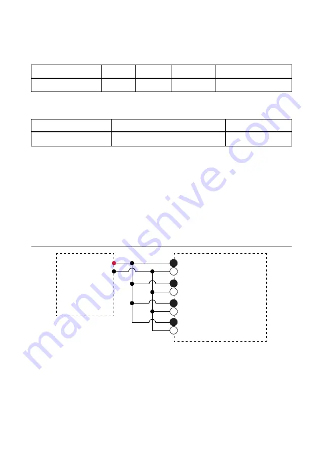
10. Connect the calibrator to Bank 2 of the FD-11603, as shown in the following figure.

Refer to 

Signal Connector Pinout

 for signal connection information.

Figure 3. Bank 2 Verification Connections

AI 0+
AI 0–

HI

LO

AI 1+
AI 1–

Calibrator

FD-11603

AI 2+
AI 2–

AI 3+
AI 3–

Bank 2

2

4

2

4

2

4

2

4

Tie AI 0+, AI 1+, AI 2+, and AI 3+ together.

Tie AI 0-, AI 1-, AI 2-, and AI 3- together.

11. Complete Steps 3 through 9 for Bank 2 using FD11603-Bank2/ai0:3 as the physical

channel.

6

  | 

ni.com

  | 

FD-11603 Calibration Procedure

Summary of Contents for FD-11603

Page 1: ...inout 9 Where to Go for Support 10 Software Requirements Calibrating the FD 11603 requires the installation of NI DAQmx on the calibration system NI recommends using the latest NI DAQmx driver Earlies...

Page 2: ...ovides detailed specifications for your FieldDAQ device NI DAQmx Readme Provides operating system and application software support in NI DAQmx NI DAQmx Help Provides information about creating applica...

Page 3: ...d wires act as antennas picking up extra noise that can affect measurements Verify that all connections to the device are secure Use shielded copper wire for all cable connections to the device Use tw...

Page 4: ...ng the Device in MAX When the FieldDAQ device is connected to a network multiple users can access the device To perform any DAQ functionality on the device including reset and self test you must reser...

Page 5: ...alue determined by the array of recommended calibration voltages indicated in the following table Table 3 FD 11603 Test Limits Test Point 1 Year Limits Location Value V Lower Limit V Upper Limit V Neg...

Page 6: ...samples e Average the readings f Clear the task 6 Set the calibrator to Standby mode STBY 7 Compare the average to the limits in Table 3 8 Repeat steps 3 through 7 for each test point 9 Disconnect the...

Page 7: ...n degrees Celsius using the Set Temperature FieldDAQ function b Call the Get FD 11603 Calibration Adjustment Points function c Set the calibrator to a reference value determined by the array of adjust...

Page 8: ...Initialize External Calibration function to start a calibration session on the FieldDAQ device The default password is NI 2 Call the DAQmx Set Temperature FieldDAQ Calibration function to input the ex...

Page 9: ...fic calibration conditions described in this document and are not to be construed as general operational specifications of the FD 11603 For operational specifications refer to the most recent FD 11603...

Page 10: ...nd Logo Guidelines at ni com trademarks for information on NI trademarks Other product and company names mentioned herein are trademarks or trade names of their respective companies For patents coveri...

Reviews: