


© National Instruments
|
5-7
cDAQ-9185/9189 User Manual
Digital Input Filters
When performing a hardware timed task, you can enable a programmable debouncing filter on the
digital input lines of a parallel DIO module. All lines on a module must share the same filter
configuration. When the filter is enabled, the chassis samples the inputs with a user-configured
Filter Clock derived from the chassis timebase. This is used to determine whether a pulse is
propagated to the rest of the system. However, the filter also introduces jitter onto the input signal.
In NI-DAQmx, the filter is programmed by setting the minimum pulse width,
Tp
1
, that will pass
the filter, and is selectable in 25 ns increments. The appropriate Filter Clock is selected by the
driver. Pulses of length less than 1/2
Tp
will be rejected, and the filtering behavior of lengths
between 1/2
Tp
and 1
Tp
are not defined because they depend on the phase of the Filter Clock
relative to the input signal.
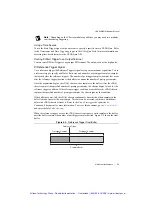
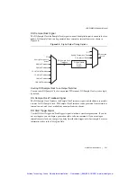
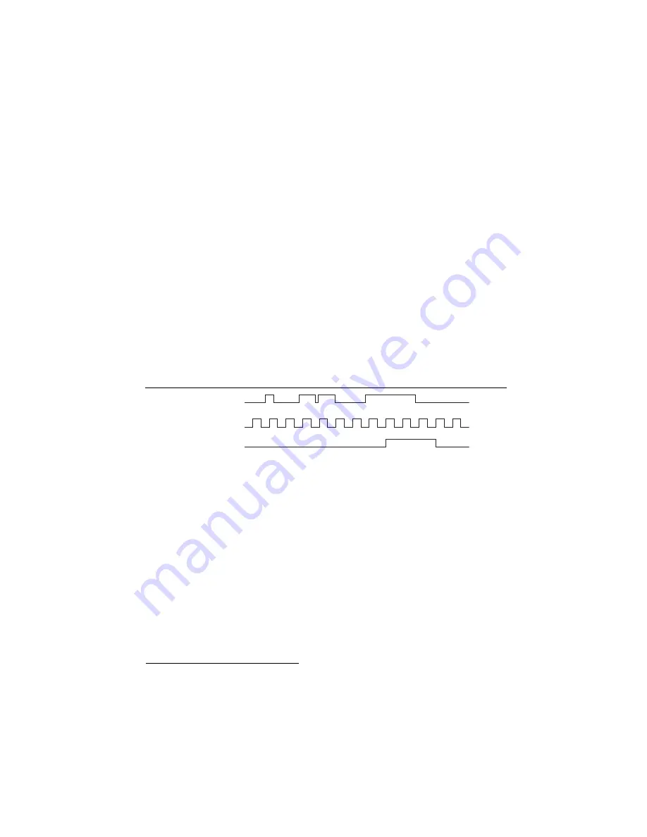
Figure 5-3 shows an example of low-to-high transitions of the input signal. High-to-low
transitions work similarly.
Assume that an input terminal has been low for a long time. The input terminal then changes
from low to high, but glitches several times. When the filter clock has sampled the signal high
on consecutive rising edges, the low-to-high transition is propagated to the rest of the circuit.
Figure 5-3.
Filter Example
Getting Started with DI Applications in Software
You can use the cDAQ chassis in the following digital input applications:
•
Single-point acquisition
•
Finite acquisition
•
Continuous acquisition
For more information about programming digital input applications and triggers in software,
refer to the
NI-DAQmx Help
or the
LabVIEW Help
for more information.
1
Tp
is a nominal value; the accuracy of the chassis timebase and I/O distortion will affect this value.
Digit
a
l Inp
u
t P0.
x
Filter Clock
Filtered Inp
u
t
1
1
2
1
1
2
1
Artisan Technology Group - Quality Instrumentation ... Guaranteed | (888) 88-SOURCE | www.artisantg.com