Getting Started with AKD EtherCAT Drives and NI SoftMotion
|
© National Instruments
|
9
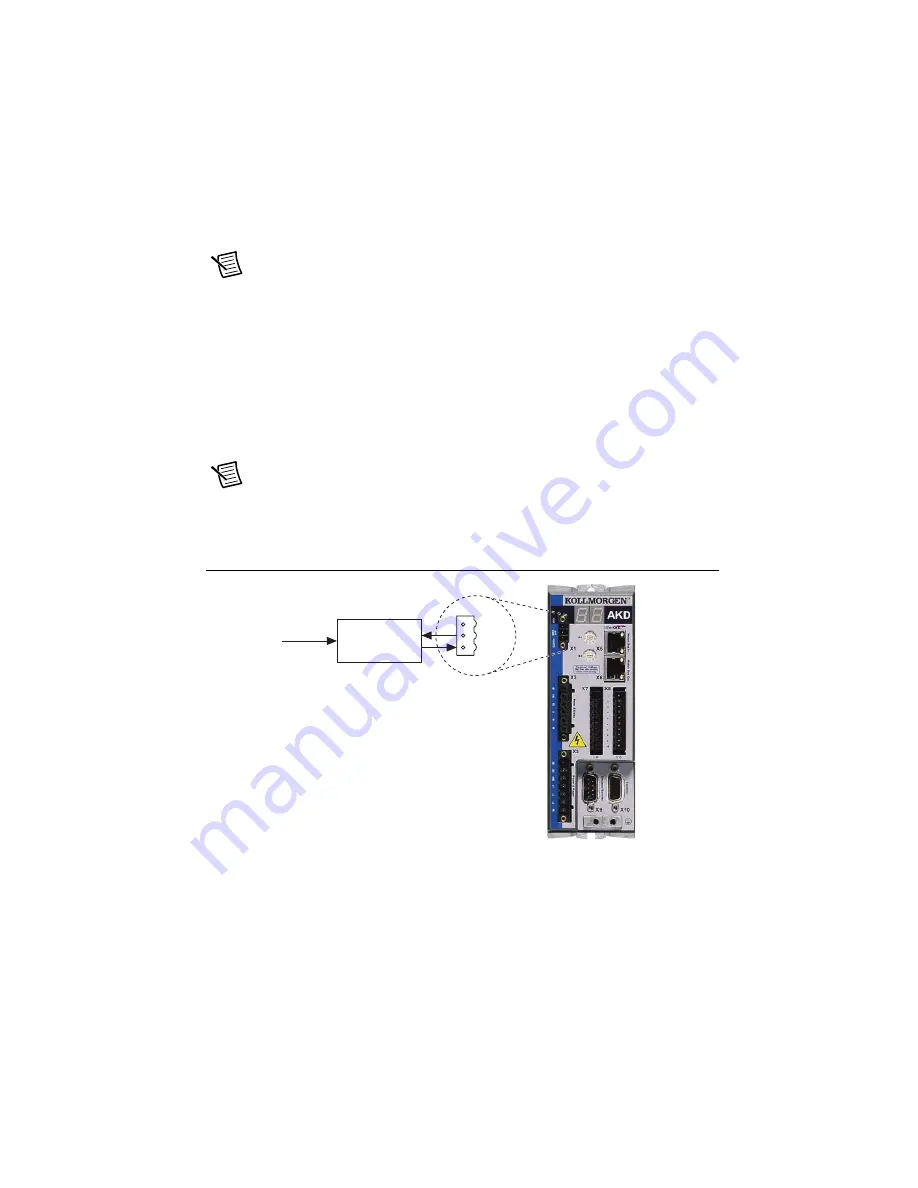
Connect the Logic Power Supply to the X1 Connector
The +24 V power supply provides the logic power to the AKD EtherCAT servo drive. Complete
the following steps to connect the +24 V power supply to the drive.
Note
Do not plug in or turn on the +24 V power supply until all required hardware
connections are made.
1.
Connect the +24 V power supply (+) terminal to the +24 terminal on the AKD X1
connector.
2.
Connect the +24 V power supply return (-) terminal to the GND terminal on the AKD X1
connector.
3.
Connect the STO terminal and GND terminal to the output of a safety relay or security
control. The safety relay must comply with the requirements of the SIL 2 according to
IEC 61800-5-2, PL d according to ISO 13849-1, or Category 3 according to EN-954. Refer
to the
AKD Installation Manual
for more information.
Note
If the STO functionality is not required, connect the STO terminal directly to
the +24 terminal on the AKD X1 connector to bypass any external safety circuitry.
Figure 7 shows the AKD EtherCAT servo drive X1 connector pinout.
Figure 7.
AKD X1 Connector
Connect the Hardware Enable on the X8 Connector
The Enable input (X8, pin 4) requires external connection to enable the output stage on the drive.
The enable signal allows either a sinking or sourcing configuration. Refer to Figure 9 for the X8
connector pinout. Refer to Chapter 8,
Electrical Installation
, in the
AKD Installation Manual
for
connection information.
1
2
3
+24
GND
S
TO
Sa
fety Rel
a
y
or
S
ec
u
rity Control
Interlock


