background image

8

|

ni.com

|

Getting Started with AKD EtherCAT Drives and NI SoftMotion

Step 2: Connect the AKD EtherCAT Drive

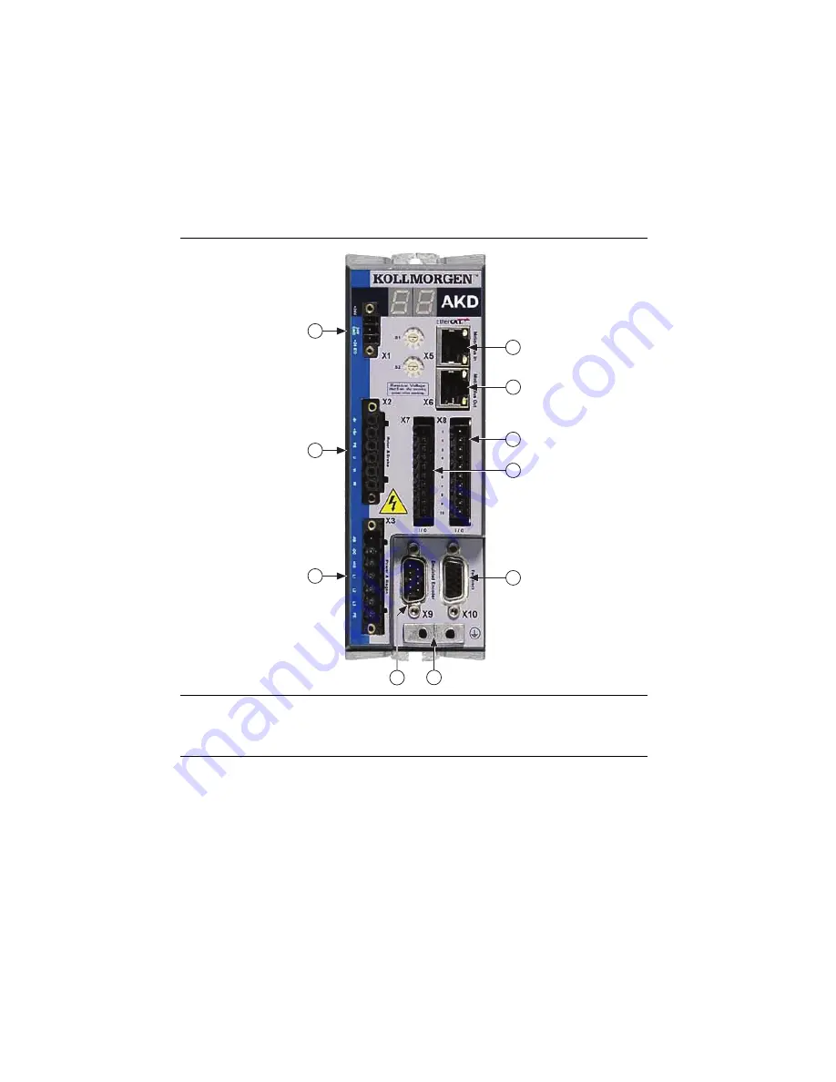
Figure 6 shows an overview of the connectors on the AKD EtherCAT servo drive.

Figure 6.  

AKD EtherCAT Servo Drive Connectors

Mount the Drive and Connect the Protective Earth

1.

Mount the drive to a conductive metal plate. Refer to the 

AKD Installation Manual

 for 

dimensions and additional information specific to the drive model. 

2.

Connect the protective earth (PE) to either ground screw on the drive grounding lug. 
Figure 6 shows the location of the grounding lug on the drive.

1

24 V Supply, STO (X1)

2

Motor, Brake (X2)

3

AC Input Power (X3)

4

Encoder Emulation (X9)

5

Drive Grounding Lug

6

Feedback (X10)

7

I/O Connector (X7)

8

I/O Connector (X8)

9

Motion Bus OUT (X6)

10 Motion Bus IN (X5)

1

2

3

6

10

8

5

7

9

4

Summary of Contents for AKD EtherCAT

Page 1: ...ftMotion Module Overview 4 Hardware and Software Configuration 4 Step 1 Set Up the CompactRIO System 5 Step 2 Connect the AKD EtherCAT Drive 8 Step 3 Install Software on and Configure the NI RT Controller 14 Step 4 Creating a Project and Adding an NI SoftMotion Axis 16 Step 5 Install Kollmorgen WorkBench and Configure the Drive 19 Step 6 Tune the System using Kollmorgen WorkBench 22 Step 7 Configu...

Page 2: ... for EtherCAT use NI PXI 8231 NI PXI 8232 NI Industrial Controller 24 VDC power supply for the CompactRIO controller or Industrial Controller not applicable for PXI controllers 24 VDC power supply for the AKD EtherCAT servo drive Note Check your hardware documentation for power supply requirements Ethernet connection and cable for the RT controller Ethernet cable and EtherCAT connection for the AK...

Page 3: ...D Installation Manual Use this document to learn additional information about the electrical and mechanical aspects of the AKD EtherCAT servo drive including important safety information Documentation for the CompactRIO or PXI controller shipped with the hardware and available at ni com manuals LabVIEW NI SoftMotion Module Help Use this help file to learn about using the NI SoftMotion Module in La...

Page 4: ... building debugging and deploying real time applications Access the Getting Started with the LabVIEW Real Time Module PDF by selecting Start All Programs National Instruments LabVIEW LabVIEW Manuals RT_Getting_Started pdf NI SoftMotion Module Overview The LabVIEW NI SoftMotion Module allows you to create deterministic motion control applications using the LabVIEW Development System The following f...

Page 5: ...oftware Configuration This section covers the hardware and software setup for the EtherCAT master and AKD EtherCAT servo drive and contains instructions about using the NI SoftMotion Module to configure and test your system Note This document uses a CompactRIO controller as the EtherCAT master Refer to Configuring a PXI or Industrial Controller Master for setup instructions for those devices The f...

Page 6: ...rial number after you have mounted the controller a Make sure that no power is connected to the controller or the chassis b Align the controller with the chassis as shown in Figure 3 Figure 3 Installing the Controller on the Chassis Eight Slot Chassis Shown c Slide the controller onto the controller slot on the chassis Press firmly to ensure the chassis connector and the controller connector are m...

Page 7: ... 5 Ethernet cable The secondary port is the top port LAN PORT 2 You may expand the deterministic Ethernet network by connecting an additional AKD EtherCAT drive or other slave devices to the X6 Motion Bus OUT port bottom port on the first AKD EtherCAT drive Figure 4 Connecting the AKD EtherCAT Drive to the Network The LED indicators on the AKD Motion Bus IN and Motion Bus OUT ports display the com...

Page 8: ...to a conductive metal plate Refer to the AKD Installation Manual for dimensions and additional information specific to the drive model 2 Connect the protective earth PE to either ground screw on the drive grounding lug Figure 6 shows the location of the grounding lug on the drive 1 24 V Supply STO X1 2 Motor Brake X2 3 AC Input Power X3 4 Encoder Emulation X9 5 Drive Grounding Lug 6 Feedback X10 7...

Page 9: ... relay must comply with the requirements of the SIL 2 according to IEC 61800 5 2 PL d according to ISO 13849 1 or Category 3 according to EN 954 Refer to the AKD Installation Manual for more information Note If the STO functionality is not required connect the STO terminal directly to the 24 terminal on the AKD X1 connector to bypass any external safety circuitry Figure 7 shows the AKD EtherCAT se...

Page 10: ...ors 1 Connect the motor 6 pin connector to the AKD EtherCAT servo drive X2 Motor connector Note The X2 connector also provides connection for the drive to control the 24 V holding brake for motors that have a brake Refer to the AKD Installation Manual for information about the holding brake if your motor contains an internal brake 2 Connect the motor DSUB feedback connector to the AKD EtherCAT ser...

Page 11: ...ans that Digital Input 1 on the AKD corresponds to DI0 in the NI SoftMotion software Table 1 shows the preset signal mapping for the AKD EtherCAT servo drive in the NI SoftMotion software You can connect the AKD EtherCAT servo drive to sourcing or sinking digital output devices depending on how the DCOM terminal on each connector is wired Sourcing Connect DCOM to the negative terminal on the 24 V ...

Page 12: ...uired hardware connections are made Figure 10 shows the location and pin assignment for the X3 connector Figure 10 AKD EtherCAT Servo Drive X3 Connector AC input power can be connected for either a three phase or single phase operation Note External filtering and fusing are optionally provided by the user Refer to the AKD Installation Manual for information about filter and fuse requirements Figur...

Page 13: ...y d Drive status either the operation mode or the fault or warning code if there is a fault or warning condition The operation modes are as follows o0 torque mode current mode o1 velocity mode o2 position mode Note If the drive shows a fault or warning code refer to the AKD Fault and Warning Messages Card that came with the drive or the NI SoftMotion Module Help for more information about the faul...

Page 14: ...ler to the On position 6 Power on the controller If it is already powered on press the Reset button on the controller to reboot it 7 Right click the controller under Remote Systems in the Configuration pane and select Format Disk Click Yes on the dialog box that appears 8 When MAX finishes formatting the disk set the Safe Mode switch to the Off position and press the Reset button on the controller...

Page 15: ...s in the eth1 section 17 Select EtherCAT from the Adapter Mode list Note These settings are not available if NI Industrial Communications for EtherCAT is not installed to the target 18 Some RT controllers can configure the Packet Detection of the Ethernet Adapter If the option is available for your target in the eth0 Primary section click More Settings and change Packet Detection to Polling Leave ...

Page 16: ...e block diagram 6 Right click the top level project item in the Project Explorer window and select New Targets and Devices from the shortcut menu to display the Add Targets and Devices dialog box 7 Make sure that the Existing target or device radio button is selected 8 Expand Real Time CompactRIO Real Time PXI or Real Time Industrial Controller as appropriate for your hardware 9 Select the control...

Page 17: ...drive does not appear in the Project Explorer window after this step confirm that the NI Scan Engine is in Configuration mode and repeat steps 11 and 12 Refer to the Tips and Troubleshooting section for more information 13 Right click the controller item in the Project Explorer window and select Properties from the shortcut menu to display the RT Target Properties dialog box Select Scan Engine fro...

Page 18: ... axis associated with the AKD EtherCAT drive Axes are automatically bound to an available drive You can double click the axis name to rename the axis and give it a descriptive name 17 Click OK to close the Axis Manager dialog box The new axis is added to the Project Explorer window Note You cannot associate more than one axis with the same AKD EtherCAT drive When you have finished these steps your...

Page 19: ...2 Double click Full Setup exe to launch the installer 3 Follow the onscreen instructions to complete the installation Complete the following steps to configure the drive settings with Kollmorgen WorkBench 1 Launch the Kollmorgen WorkBench software by clicking the Kollmorgen WorkBench icon on the desktop or by selecting Start All Programs Kollmorgen Kollmorgen WorkBench 2 Select the drive to config...

Page 20: ...etting Started with AKD EtherCAT Drives and NI SoftMotion Figure 17 shows the Kollmorgen WorkBench Start page Figure 17 Kollmorgen WorkBench Start Page 1 Available Drives 2 Specify Address 3 Connect to Drive 1 3 2 ...

Page 21: ...the default values 4 Optional Change the name of the drive from the default name of no_name on the AKD Overview page to a more descriptive name Figure 18 shows the AKD Overview page Figure 18 Kollmorgen WorkBench Overview Page 1 Software Enable Disable 2 Command Source 3 Operation Mode 4 Clear Faults 5 Save Configuration Settings to Drive 6 Software Enable Disable 7 Drive Active Indicator 8 Softwa...

Page 22: ...ning the drive with WorkBench refer to the Tuning Your System topic in the installed Kollmorgen WorkBench Help Step 7 Configure the AKD EtherCAT Servo Drive Axis In this section you will configure the axis associated with your AKD EtherCAT servo drive using the Axis Configuration dialog box Complete the following steps to configure the axis I O settings for use with the AKD EtherCAT servo drive 1 ...

Page 23: ...nfigured settings to the drive This is unselected by default as the default drive settings work well for most applications When selected the drive settings will be overwritten by the Velocity Loop settings Position Loop gains and Brake settings configured with the Axis Configuration dialog box National Instruments recommends leaving this option unselected and using WorkBench to configure the drive...

Page 24: ...close the Axis Configuration dialog box Caution Make sure all hardware connections are made and power is turned on before deploying the project Deployment may switch the NI Scan Engine to Active mode Refer to the Deploying and Running VIs on an RT Target topic in the LabVIEW Help for more information about deployment and for troubleshooting tips 8 Right click the controller item in the Project Exp...

Page 25: ...nd Plots tabs to monitor the move while it is in progress Your system is now configured and ready for motion application development Configuring a PXI or Industrial Controller Master Complete the following steps to use a PXI or Industrial Controller as the EtherCAT master 1 Connect the controller to an Ethernet network on the same subnet as the development computer Refer to the controller operatin...

Page 26: ...s in this document the AKD EtherCAT servo drive does not enable verify the following settings Make sure that the hardware enable is connected to the 24 V power supply as described in Connect the Hardware Enable on the X8 Connector The software enable must be enabled Verify that the NI Scan Engine is in active mode and that Drive Enable is active You can use the Interactive Test Panel dialog box or...

Page 27: ...ded to the LabVIEW Project The NI Scan Engine must be in Configuration mode to detect and add EtherCAT slave devices to the EtherCAT bus Complete the following steps to check and switch the NI Scan Engine mode 1 Right click the EtherCAT master and select View in System Manager from the shortcut menu 2 In the Scan Engine Mode section check the Scan Engine mode If the Scan Engine mode is Active clic...

Page 28: ...GITAL IN6 NSTOP AGND DGND DGND Fault Feedback Thermal Control Included Reference Safety Instructions and Use As Directed Br RB DC L1 L2 L3 PE 24V STO GND RB DC Br PE U V W ENABLE Analog In Referred to I O GND I O GND Emergency Stop Circuit Digital1 Digital2 10V Speed Setpoint 10V 24V Referred to I O GND 24V Referred to I O GND I O GND Control Tachometer Voltage Chassis Ground Connection Panel PE C...

Page 29: ... with the Council of the European Communities using the manufacturer s declaration of conformity This system affords the user protection for electromagnetic compatibility EMC and product safety You can obtain the DoC for your product by visiting ni com certification If your product supports calibration you can obtain the calibration certificate for your product at ni com calibration NI corporate h...

Page 30: ...can find information about end user license agreements EULAs and third party legal notices in the readme file for your NI product Refer to the Export Compliance Information at ni com legal export compliance for the NI global trade compliance policy and how to obtain relevant HTS codes ECCNs and other import export data NI MAKES NO EXPRESS OR IMPLIED WARRANTIES AS TO THE ACCURACY OF THE INFORMATION...

Reviews: