background image

Machine Operation

FIG. D

LOADING/UNLOADING

SAFETY PRECAUTIONS

• 

Always remove blade and cutting head when machine is being moved or trans-
ported.

• 

Cutting head and slide plate can be removed to make the machine more compact.

• 

NEVER leave machine unattended on an incline.

• 

Removing added weights help to make the machine easier and safer to move in 
and out of a vehicle.

DOCK HEIGHTS

It is best to load or unload the machine from a level/equal dock height (a van from a van 
dock height, a truck/semi from a regular dock height).

POWER-GATE

A power-gate can be used when the dock height is not available. Make sure gate is prop-
erly rated for 1365 kg (3000 lb). Make certain the machine is secure so it does not roll off 
the power-gate. To better secure machine, raise machine onto the lowered cutting head, 
raising machine off the caster. Tie machine down, chock wheels. 

RAMPS

To be safe, the ramp needs to be long to accommodate the machine being loaded/
unloaded. Only use a ramp designed and rated for 1365 kg (3000 lb) or more. Remove 
added weight. Do not have at a steep incline. The use of a power winch or hand come-
a-long is much safer. For a van, the ramp should be 4 to 6 meters (12 to 16’) in length 
depending on the depth of the incline. For truck height taller than a van, longer ramps will 
be needed. See OSHA guidelines. It is not recommended to drive the machine, connect-
ed with power, on a ramp. Make sure ramp is secure and has good contact before using. 
Failure to do so could cause ramp to fall away from the vehicle. 

FORKLIFT CUPS

There are two forklift cups mounted under the front of the machine (Figure F). Slide fork 
lift forks through forklift cups. Slide forks all the way back to touch the rear tire (Figure G). 
Before lifting machine, secure machine to fork lift with heavy 1365 kg (3000 lb) or heavier 
straps or chain. Tilt forks back to lift machine (Figure H).

WINCHES

Winches should be used for safety when loading or unloading with ramps. 1365 kg (3000 
lb) winch minimum.

FIG. E

FIG. F

FIG. G

Fax: 763-535-8255

[email protected]

13

FIG. H

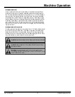
WARNING:

 MACHINE HAS A SWIVEL FRONT CASTER. NEVER SIDE HILL 

(FIGURE A). THE MACHINE ON A INCLINE WITHOUT POWER, THE FRONT 
CASTER WILL CAUSE MACHINE TO SWING TO THE LOWEST POINT. IF IT IS 
NECESSARY TO RUN MACHINE ON AN INCLINE, RUN MACHINE ON CUTTING 
HEAD. PLACE AT LEAST A 8’’ CUTTING HEAD IN MACHINE. TO KEEP FROM 
DAMAGING FLOOR, CLAMP A PIECE OF CARPET INTO CUTTING HEAD TO 
SLIDE ON THE FLOOR. THIS WILL GIVE POSITIVE CONTACT WITH THE 
FLOOR WHEN POWER IS DISENGAGED FROM THE WHEELS.

CAUTION:

 MACHINE IS BACK HEAVY. DO NOT RUN ON STEEP INCLINE THIS 

COULD CAUSE MACHINE TO TIP OVER! (FIGURE E)

Fork Lift Cup

CAUTION: DO NOT SIDE HILL

Caution: Machine is back heavy. Do not run on steep incline. 

This could cause machine to tip over.

Summary of Contents for 5700-aus

Page 1: ...Read Manual Before Operating Machine ALL DAY BATTERY RIDE ON SCRAPER INSTRUCTION MANUAL Rev B 401810...

Page 2: ......

Page 3: ...Heads 22 Types of Blades 22 24 Blade Sharpening 25 Machine Maintenance 26 29 Manual Slide Plate Removal 26 Raising or Lowering Manual Slide Plate 26 Dual Slide Plate Removal 26 Checking Oil Level 27...

Page 4: ...63 535 8255 info nationalequipment com 4 Gear Pump Assembly 40 Labels 41 Weights Wrench 42 Battery Wiring 43 Seat Wiring 44 Machine Wiring 45 Accessories 46 47 Material Safety Data Sheet MSDS Informat...

Page 5: ...230 volts it charges the 12 AGM batteries overnight Adjustable Slide Plate Affords maximum versatility in blade set tings Fork Lift Cups Make it easier to load and unload on jobsites Control Levers F...

Page 6: ...g of moving parts improper mounting broken parts and other conditions that may affect operation If abnormal noise or vibration occurs turn off immediately and have the problem corrected before further...

Page 7: ...pressure Performs correctly when supervised or not HYDRAULIC SAFETY TIPS MAINTAININGASAFE WORK ENVIRONMENT Establishing a safe work environment around your hydraulic equipment is paramount to safe and...

Page 8: ...attempt the start up procedure with out being seated on the machine BATTERY Contact with electrolytic acid can cause skin irritation and damage clothing Wear a protective apron gloves and goggles when...

Page 9: ...being used on the charger and keep it as short as possible The use of an improper extension cord could result in a risk of a fire or electric shock Locate all cords so that they will not be stepped on...

Page 10: ...g 5 Release E Stop BUILT IN LOW VOLTAGE INTERRUPT One of the most common causes of premature battery failure is over discharging Low Voltage Interrupter and alarm continuously monitors for low voltage...

Page 11: ...o 2 years without being used or charged 6 Question Does severe cold effect the batteries Answer If fully charged no If allowed to warm up room temperature battery will perform better If battery is und...

Page 12: ...tch Connect charger to a battery s with the same voltage rating When powered up LED is solid red with a yellow flash Battery is very low and charger is in a slow charge phase until the voltage rises t...

Page 13: ...will be needed See OSHA guidelines It is not recommended to drive the machine connect ed with power on a ramp Make sure ramp is secure and has good contact before using Failure to do so could cause r...

Page 14: ...gravity changes Too much of an angle could make the machine unsafe a cause for tip over Do Not run the machine in unsafe environments JOB SITE MOVEMENT TAPING WHEELS Taping the wheels with a wide like...

Page 15: ...ward move the machine forward Both levers backward move the machine backward The left lever forward and the right lever backward turn the machine quickly to the right The left lever backward and the r...

Page 16: ...l Assembly can seem to make the machine turn sluggish It might turn hard to the right or the left This is normal FOOT PEG Keep feet resting and secured on foot pegs when operating machine Foot pegs ar...

Page 17: ...ing the angle or pitch of the cutting head holder Pull back on the cutting head lever and raise the cutting head holder to an angle higher than the bottom of the slide plate Using the lever adjacent t...

Page 18: ...e bottom of the slide plate is higher or even with the bottom of the guide channels Figure X Rais ing the slide plate to an angle too steep when operating will cause the machine to jump and buck It do...

Page 19: ...ades Figure EE for soft sub floors KEEP BLADES SHARP Dull blades greatly affect the performance of the machine and reduce cutting ability resharpen or replace as needed After you have removed a portio...

Page 20: ...le over the tile This should help to save the tile VCT TILE SET UP The slide plate should be adjusted to a low setting 2 5 cm 1 off the floor If goods come up easily change to a larger Cutting Head If...

Page 21: ...he blade flat Approach should be at a 45 angle to the board This keeps from digging into the board and hang ing up at the seams WORKING OVER SOFT SUB FLOOR The slide plate should be adjusted to a low...

Page 22: ...or floor accumulations 7050 200 3 X 6 PREMIUM HIGH TEMPERED BLADE 062 7050 201 3 X 8 PREMIUM HIGH TEMPERED BLADE 062 7050 202 3 X 10 PREMIUM HIGH TEMPERED BLADE 062 7050 203 3 X 12 PREMIUM HIGH TEMPER...

Page 23: ...E SHANK BLADES FIGURE PP Works well for ceramic and thick epoxy The same application as the 7070 blades but is mounted at an angle to achieve the optimum shear point for optimum performance 7071 2 4 X...

Page 24: ...78 BU 3 X 14 SELF SCORING BLADE 094 6279 BU 3 X 27 SELF SCORING BLADE 094 6247 4 X 10 SELF SCORING BLADE 094 6249 4 X 12 SELF SCORING BLADE 094 6248 4 X 24 SELF SCORING BLADE 094 6256 BU 4 X 6 W 4 BU...

Page 25: ...help to make the removal easier Using a blade 5 to 16 cm 2 to 6 in width make ditches 1 to 2 apart in the same direction the machine will be removing the goods See Figure EE This relieves the pressur...

Page 26: ...IFT SLIDE PLATEAND CUTTING HEAD For safety prior to adjusting the dual lift hydraulic slide plate make sure the channel guide is free of any debris and the machine is safely positioned on a flat surfa...

Page 27: ...AL 1 Disconnect machine from power 2 Remove hood 3 Using proper wrench size remove hose from fitting 4 When replacing make sure O ring is properly seated on hose fitting WHEEL MOTOR CHANGE OUT 1 Disco...

Page 28: ...from lower cutting head support 4 Remove clips and pin from cylinder and slide plate 5 Remove cylinder upper pin 6 Remove cylinder CHANGING FILTER FILTER SHOULD BE REPLACED YEARLY 1 Place pan or rag b...

Page 29: ...at plate unplug wire harness 3 Lift hood off 4 Remove seat 5 To replace seat set seat on top of hood 6 Replace the four 3 8 x 16 x 3 4 hexhead screws from underneath the hood 7 Firmly tighten 8 Reconn...

Page 30: ...hardware on machine Inspect and tighten bolts as needed Charger is hot Charger is in use This is normal Fluid is leaking from machine Hose connections or fittings have loosened through normal use Tigh...

Page 31: ...AULIC 10MM BOLT2 50 400327 HANDLE RUBBER COVER 1 51 400364 HANDLE HOLDER WELDMENT LH 1 52 401401 HANDLE HOLDER WELDMENT RH 1 53 401403 LEVER BRACKET 1 54 401429 PIN CUTTING HEAD 1 55 401553 BATTERY CH...

Page 32: ...D4 PUMP DOUBLE MARZOCCHI 1 126 L08 1 LABEL STAND CLEAR 2 127 L106 LABEL PINCH POINT 2 128 L118 LABEL OPERATOR MUST BE SEATED 2 129 L127 LABEL CAUTION OPERATING 1 130 L137 LABEL DISARM MACHINE 2 131 L1...

Page 33: ...1 9 401571 TUB WELDMENT 1 10 401572 COVER BATTERY UPPER 1 11 401570 TRAY BATTERY UPPER 1 12 5600 21 HANDLE WELDMENT RIGHT 1 13 5600 22 HANDLE WELDMENT LEFT 1 14 73212 BOLT BUTTON HEAD CAP 3 8 16X1 2 2...

Page 34: ...67 HOSE CYLINDER 1 8 5700 36 GUARD HOSE 2 9 73334 BOLT HEX HEAD CAP 5 16 18X1 1 2 3 10 73322 NUT NYLOCK 5 16 18 2 PART DESCRIPTION QTY CYLINDER ASSEMBLY 6 7 8 5 3 4 1 2 10 9 1 6500 11 PLATE SLIDE DUAL...

Page 35: ...LOCK 1 2 4 PART DESCRIPTION QTY CASTER WHEEL ASSEMBLY 1 2 1 400133 MOTOR WHEEL HYDRAULIC 10MM BOLT2 2 5110 114 2 FITTING WHEEL MOTOR 4 3 5110 117 WHEEL HUB 2 4 5110 117 2 NUT HUB 2 5 5200 261 1A CLAMP...

Page 36: ...PLUG 48V 1 7 5700 85 COVER TERMINAL STRIP 1 8 5700 80 HARNESS MAIN 1 9 71703 PROTECTOR BATTERY TERMINAL RED 3 10 5700 90 RELAY SOCKET 1 11 5700 91 RELAY 1 12 72834 PROTECTOR SMALL 2 PART DESCRIPTION Q...

Page 37: ...PS PAN HEAD MAC 6 32X1 2 PART DESCRIPTION QTY 1 70602 TUBE INSTRUCTION MANUAL 1 2 70603 CAP INSTRUCTION TUBE 1 3 74425 NUT KEPS LOCK 10 32 2 PART DESCRIPTION QTY 1 5110 180 PEG FOOT 2 2 73238 BOLT FLA...

Page 38: ...ASSEMBLY HOSE 1 14 5700 81 HOSE SUCTION LINE 1 15 70905 D4 PUMP DOUBLE MARZOCCHI 1 16 5700 65 FILTER 1 17 5700 66 FILTER HEAD 1 18 70653 FITTING 90 DEGREE 2 19 70354 HOSE 3 4 RETURN LINE TO TANK 1 20...

Page 39: ...List and Diagrams Fax 763 535 8255 info nationalequipment com 39 HYDRAULIC FLOW DIAGRAM 11 8 4 7 24 10 13 14 17 25 16 15 3 14 23 12 2 1 18 19 20 21 22 THEASSOCIATED NUMBERS FOR THESE CALLOUTSARE ON PA...

Page 40: ...HEX HEAD CAP 3 8 16X1 2 6 73204 WASHER SPLIT LOCK 3 8 2 7 5700 35 SPACER MOTOR 2 PART DESCRIPTION QTY 1 70905 D4 PUMP DOUBLE MARZOCCHI 1 2 5200 1G GASKET PUMP 1 3 72816 FITTING ELBOW 90 DEGREE 3 8 2 4...

Page 41: ...ANDLE HOLDER WELDMENT LH 1 9 5700 54 HANDLE PLASTIC TUBE 1 10 400327 HANDLE RUBBER COVER 1 11 73020 1 4 20X5 8 WIZLOCK BOLT 3 12 73202 3 8 INTERNAL LOCK WASHER 6 13 73213 3 8 16X3 4 BUTTON HEAD CAP SC...

Page 42: ...2 6 L155 LABEL GENERAL WARNING 1 7 L223 LABEL PATENT NUMBER 1 8 L305 LABEL DO NOT GET CHARGER WET 1 9 L309 LABEL A 6 10 L310 LABEL B 6 11 L311 2 LABEL BATTERY 12 12 L33B LABEL CAUTION MOVING PART 1 13...

Page 43: ...GHT 36 LB REMOVABLE 5 2 73424 WASHER FLAT ZINC SAE 1 2 7 3 73403 WASHER SPLIT LOCK 1 2 7 4 73414 BOLT HEX HEAD 1 2 13X7 1 5 73406 SCREW CAP HEXHEAD 1 2 13 X 1 1 4 1 1 5700 105 BATTERY FUEL GAUGE 1 1 5...

Page 44: ...Parts List and Diagrams Fax 763 535 8255 info nationalequipment com 44 5700 BATTERY WIRING...

Page 45: ...Parts List and Diagrams E STOP START SEAT SWITCH WHITE RED BATTERY METER BLUE BLUE HOUR METER RED BLACK RED BLACK R E D Brown Brown www nationalequipment com Phone 763 315 5300 45 5700 SEAT WIRING...

Page 46: ...Parts List and Diagrams Fax 763 535 8255 info nationalequipment com 46 5700 MACHINE WIRING...

Page 47: ...e 7050 27 Cutting Head required Part 5110 100 Allows stability and safe transportation over any surface Easy and quick to attach 5110 100W Replacement Wheel Only Part 7050 15 Extension for cutting hea...

Page 48: ...e height of the slide plate and allows precise angle adjust ment of the cutting head with hydraulic hand control No need to get off the machine no lifting and no manual labor required to adjust the pl...

Page 49: ...cid Battery Manufacturer s Name Fullriver Battery Manufacture Co Ltd Address P O Box 511475 Taishi Industrial Area Yuwotou Town Panyu Zone Guangzhou China Chemical Family Classification Electric Stora...

Page 50: ...pounds May cause eye irritation EFFECTS OF OVEREXPOSURE ACUTE Sulfuric Acid Severe skin irritation damage to cornea upper respiratory irritation Lead Compounds Symptoms of toxicity include headache fa...

Page 51: ...of any circuit connections If batteries are properly charged they will not release any flammable hydrogen gas If they are excessively overcharged the safety relief valve can open and release flammabl...

Page 52: ...Acid Sulfur trioxide carbon monoxide sulfuric acid mist sulfur dioxide and hydrogen Lead Compounds High temperatures likely to produce toxic metal fume vapor or dust contact with strong acid or base...

Page 53: ...he recommended mineral oil mist exposure limit Symp toms of respiratory irritation may include coughing and difficulty breathing FIRST AID MEASURES Eye No specific first aid measures are required As a...

Page 54: ...lying respira tor in circumstances where air purifying respirators may not provide adequate protection CHEVRON HD 22 68 HYDRAULIC FLUID CONTINUED www nationalequipment com Phone 763 315 5300 54 EXTING...

Page 55: ...roleum base oils which may be refined by various processes including severe solvent extractio severe hydrocracking or severe hydrotreating None of the oils requires a cancer warning under the OSHA Haz...

Page 56: ...ed by the National Fire Protection Association NFPA or the National Paint and Coating Association for HMIS ratings LABEL RECOMMENDATION Label Category INDUSTRIAL OIL 1 IND1 REVISION STATEMENT This rev...

Page 57: ...d shall be the sole and exclusive remedy available to the purchaser Correction of defects in the manner and for the period of time described herein shall constitute complete fulfillment of all liabili...

Page 58: ...800 648 7124 Fax 763 535 8255 Web Site www nationalequipment com E Mail info nationalequipment com 9250 Xylon Avenue N Minneapolis MN 55445 U S A Toll free 800 245 0267 Phone 763 315 5300 Fax 800 648...

Reviews: