34
Gas Furnace
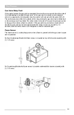
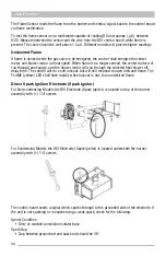
The Flame Sensor reads the flame from the burner and sends a signal back to the control board
via flame rectification.
To test the flame sensor use a multimeter capable of reading DC microamps ( µA ) between
0-20. Measure between the sensor and the wire from the DSI control board while flame is
present. The value should be well above 1.5 µA. Different models will provide higher readings.
Undesired Flame
If flame is sensed while the gas valve is de-energized, the control shall energize the venter
motor and blower motor on heat speed. When flame is no longer sensed, the venter motor will
run through post-purge, and the blower motor will run through the selected heat blower off
delay time. The control will do a soft lockout, but will still respond to open limit and flame. The
FLAME (yellow) LED shall flash rapidly when lockout is due to an undesired flame.
Direct Spark Ignition Electrode (Spark Ignitor)
For Non-condensing Models the DSI Electrode (Spark Ignitor) is located on top of the burner
assembly with (1) 1/4" screws.
For Condensing Models the DSI Electrode (Spark Ignitor) is located underneath the burner
assembly with (1) 1/4" screws.
The control board sends a signal which sparks through to the grounded side of the electrode. If
the unit is not sparking or is experiencing a weak spark, check for the following:
Ignitor Condition
• Dirty or cracked porcelain insulator base
Spark Gap
• Gap between ground rod and spark rod should be 1/8"
Summary of Contents for CPG41838-U
Page 2: ...2...
Page 5: ...5 Unit Dimensions Original R22 with Gas Heat A B Series 43...
Page 6: ...6 Original R22 with Electric Heat A B Series Unit Dimensions...
Page 7: ...7 Unit Dimensions Original R410A with Gas Heat B C D E Series...
Page 8: ...8 Unit Dimensions Original R410A with Electric Heat B C D E Series...
Page 9: ...9 Unit Dimensions U Series R410A 80 Gas Heat...
Page 10: ...10 Unit Dimensions U Series R410A up to 95 Gas Heat...
Page 11: ...11 Unit Dimensions U Series R410A Electric Heat...
Page 19: ...19 Gas Furnace 3 Remove the 11 screws 4 Remove the front furnace baffle...
Page 46: ...46 Chassis Cooling Section...
Page 79: ...79...

