15
Heat Module P/N
14208384
14208385
14208386
14208387
Input (BTU) (NG)
25,000
32,000
43,000
50,000
Output (BTU) (NG)
23,750
30,400
40,850
47,500
Input (BTU) (LP)
25,000
N/A
35,000
50,000
Output (BTU) (LP)
23,750
N/A
33,250
47,500
Max External Static Pressure (in w.c.)
0.4
0.4
0.4
0.4
Temperature Rise (°F)
30 to 60
35 to 65
35 to 65
40 to 70
Blower Speed Setting
Med. Low (4)
Med. Low (4)
Med. High (2)
High (1)
Orifice Size (NG)
51
48
50
47
Orifice Size (LP)
58
N/A
60
56
Nominal Temperature Rise (°F)
45
50
50
55
Allowable Air Temperature Range (°F)
130-160
135-165
135-165
140-170
CO
2
%- Acceptable Range
6 TO 7
6 TO 7
6 TO 7
6 TO 7
CO
1
- Air Free - ppm
0-200
0-200
0-200
0-200
Sensing Cold (in w.c.)
1.3 +/- .1
1.05 +/- .1
1.05 +/- .1
1.05 +/- .1
Stack Temperature (°F)
80-140
80-140
80-140
80-140
4. Heat Blower On Delay
– The control waits for 20 seconds from the time the gas valve
opened and then energizes the blower motor. The gas valve and venter motor remain
energized. The control proceeds to 5. Steady Heat.
5. Steady Heat
– The control continuously monitors the safeties (high limit, roll-out, and
pressure) for open switches, the flame sensor for proving, and the thermostat for a call for
heat. When the thermostat's call for heat is removed, the control de-energizes the gas valve
and begins (6.) Post-purge and (7.) Blower Off Delay.
6. Post-purge
– The venter motor output remains on for a 30-second post-purge period after
the thermostat is satisfied.
7. Blower Off Delay
– The blower motor is de-energized after a 90 second blower off delay
(field adjustable, see pages 29-31). Timing begins when the thermostat is satisfied.
Abnormal Functions
• Interrupted Thermostat Call for Heat
– If the thermostat demand for heat is removed before
the flame is recognized, the control will run the venter motor for the post purge period and
de-energize all outputs. If the thermostat demand for heat is removed after successful ignition,
the control will de-energize the gas valve, run the venter motor through post purge, and run the
blower motor on heat speed for the selected delay off time.
• Soft Lockout
– The control shall not initiate a call for heat or call a for continuous fan while
in lockout. The control will still respond to an open limit and undesired flame. Lockout shall
automatically reset after one hour. Lockout may be manually reset by removing power from the
control for more than one second or removing the thermostat call for heat for at least 1 second
but no more than 20.
• Hard Lockout
– If the control detects a fault on the control board, the status LED will be
de-energized, and the control will lockout for as long as the fault remains. A hard lockout will
automatically reset if the hardware fault clears.
• Power Interruption
– During a momentary power interruption or at voltage levels below the
minimum operating voltage for line voltage the system will self-recover without lockout when
voltage returns to the operating range. During a momentary power interruption of the 24V
control voltage, the board will enter a soft lockout. (Power interruptions of less than 80ms shall
not cause the control to change operating states. Power interruptions greater than 80ms may
cause the control to interrupt the current operating cycle and restart.)
• Ignition Retry
– If a flame is not established on the first trial for ignition, the control
de-energizes the gas valve and the venter motor remains energized for an inter-purge period of
30 seconds. The spark and gas valve are then re-energized and the control initiates another trial
for ignition. If a flame is not established on the second trial, the control de-energizes the gas
valve, energizes the blower motor on heat speed, and the venter motor remains energized. The
blower motor is shut off after a short period. When the blower motor de-energizes, the spark
and gas valve are re-energized, and the control initiates another trial for ignition. (This blower
delay is a self-healing feature for an open auxiliary limit switch). If a flame is not established on
the third trial for ignition, the control de-energizes the gas valve, and the venter motor remains
energized for an inter-purge period of 30 seconds. The control then re-energizes the spark
and gas valve and initiates another trial for ignition. If a flame is not established on the fourth
trial for ignition (initial try plus 3 re-tries), the control de-energizes the gas valve and goes
into lockout. The control displays a one flash code on the green LED to indicate ignition failure
lockout.
Gas Furnace
Summary of Contents for CPG41838-U
Page 2: ...2...
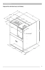
Page 5: ...5 Unit Dimensions Original R22 with Gas Heat A B Series 43...
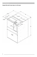
Page 6: ...6 Original R22 with Electric Heat A B Series Unit Dimensions...
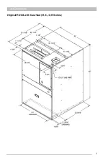
Page 7: ...7 Unit Dimensions Original R410A with Gas Heat B C D E Series...
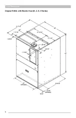
Page 8: ...8 Unit Dimensions Original R410A with Electric Heat B C D E Series...
Page 9: ...9 Unit Dimensions U Series R410A 80 Gas Heat...
Page 10: ...10 Unit Dimensions U Series R410A up to 95 Gas Heat...
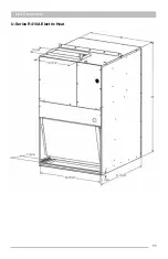
Page 11: ...11 Unit Dimensions U Series R410A Electric Heat...
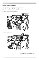
Page 19: ...19 Gas Furnace 3 Remove the 11 screws 4 Remove the front furnace baffle...
Page 46: ...46 Chassis Cooling Section...
Page 79: ...79...


