The impact of noise can cause damage to
hearing.
In operation
Vibration emission value a
h
= 6,888 m/s
2
K uncertainty = 1,5 m/s
2
Reduce noise generation and vibration to a
minimum!
•
Use only equipment that is in perfect condition.
•
Maintain and clean the equipment regularly.
•
Adopt your way of working to the equipment
. •
Do not overload the equipment.
• H
ave the equipment checked if necessary.
•
Wear gloves.
5. Assembly
Important!
Do not start the chainsaw until it has been fully
assembled and the chain tension has been
adjusted.
Always wear protective gloves when working
on the chainsaw to protect yourself against
injury.
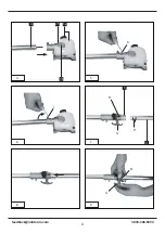
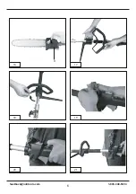
5.1 Joining the gear unit to the drive rod
mechanism (Fig. 4-6)
Tools required: Allen keys size 4mm/5mm
(supplied) Push the gear unit (Item 3b) and the
drive rod mechanism (Item 4) into each other.
Center both by turning the screw (Item K).
Important! Make sure that the screw (Item K)
is turned exactly into the guide hole (Item F).
Otherwise there is a risk of the upper part of the
rod mechanism being damaged. To join the two
subassemblies securely together, tighten the
screw (Item I). To take apart, proceed in reverse
order.
5.2 Joining the drive rod mechanism to the
connecting piece (Fig. 7-10)
Open the handle screw (Item G) and push the
drive rod mechanism (Item 4) into the connecting
piece (Item 5). Make sure that the centering lever
(Item R) latches in the guide hole (It
em H). Close
the guard cap (Item N) and tighten the handle
screw. To take apart, undo the handle screw and
open the guard cap. Press the centering lever and
simultaneously pull the drive rod mechanism out
of the connecting piece.
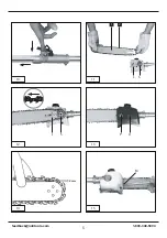
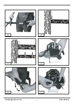
5.3 Fitting the cutter bar and the chain
(Fig. 11-16)
Tools required: Allen key size 5mm
Remove the chain wheel cover (Fig.13/ Item O)
by undoing the fastening screw (Item P). Lay the
chain (Item 2) as shown into the groove which
runs around the cutter bar (Item 1). Note the
alignment of the chain teeth (Fig. 12). Insert the
cutter bar as shown in Fig. 12 into the mount at
the gear unit. Place the chain round the chain
wheel (Item S). Make sure that the teeth of
the chain engage securely in the chain wheel.
The cutter bar must be hooked into the chain
tensioning bolt (Item L).
Fit the chain wheel cover.
Important! Do not fully tighten the fastening
screw until after you have adjusted the chain
tension (see section 5.4).
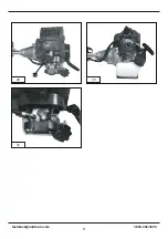
5.4 Tensioning the chain (Fig. 14-16)
Important!
Always pull out the spark boot plug
before performing any checks or adjustments.
Undo the fastening screw (Item P) of the chain
wheel cover by a few turns (Fig. 13). Adjust the
chain tension with the chain tensioning screw
(Fig. 15/Item M). Turning the screw clockwise
increases the chain tension, turning it
counterclockwise decreases the chain tension.
The chain is correctly tensioned if it can be raised
by around 2 mm in the middle of the cutter bar
(Fig. 14).
(Fig. 16).
Important! All the chain links must lie properly in
the guide groove of the cutter bar.
Notes on tensioning the chain:
The chain must be properly tensioned to ensure
safe operation. When the saw chain can be raised
by around 2 mm in the middle of the cutter bar,
you know that the chain tension is ideal. During
cutting, the temperature of the chain rises and its
1-800-348-5004
11
Summary of Contents for BlueMAX 53542
Page 4: ...4 5 4 3a 3b 25 4 6 8 5 K I N G R G H 7 9 1 800 348 5004 feedback natitools com 4...
Page 5: ...2 mm 10 12 14 11 13 15 1 2 L S L P S O M 1 800 348 5004 feedback natitools com 5...
Page 6: ...16 18 20 17 19 21 O 1 800 348 5004 feedback natitools com 6...
Page 7: ...23 25 27 24 26 a b T 22 1 800 348 5004 feedback natitools com 7...
Page 8: ...29 28 30 13 1 800 348 5004 feedback natitools com 8...


