


22
WS-415-090 / 04.03.00
Main burner flame
is a blue, lazy,
transparent flame.
Blockage in vent.
- remove blockage. In really cold conditions, ice buildup may occur
on the terminal and should be removed as required.
- refer to Figure 16 to ensure correct location of storm collars.
Incorrect installation.
TEST SOLUTION
PROBLEM
SYMPTOM
Remote wall
switch is in "OFF"
position; main
burner comes on
when gas knob is
turned to "ON" po-
sition.
Wall switch is mounted up-
side down
- reverse.
Faulty valve.
- replace.
- replace.
Remote wall switch is
grounding.
- check for ground (short); repair ground or replace wire.
Remote wall switch wire is
grounding.
Exhaust fumes
smelled in room,
headaches.
Fireplace is spilling.
- check door seal and relief flap seal.
- check for chimney blockage
- check that chimney is installed to building code.
- room is in negative pressure; increase fresh air supply.
White / grey film
forms.
Sulphur from fuel is being de-
posited on glass, logs or
combustion chamber sur-
faces.
- clean the glass with a recommended gas fireplace glass cleaner.
DO NOT CLEAN GLASS WHEN HOT.
If deposits are not cleaned off regularly, the glass may become
permanently marked.
- Restrict vent exit. See "
RESTICTING VERTICAL VENTS
".
- VENT HEIGHT LESS THAN 10 FEET: close air shutter slightly to
reduce primary air.
- VENT HEIGHT 10 TO 15 FEET: close restrictor plate by 2/3 (to 30°
open) from the normal factory setting.
- VENT HEIGHT MORE THAN 15 FEET: close restrictor plate com-
pletely from normal factory setting.
Aggressive venting action due
to vent height.
Flames are very
active.
Flames are con-
sistently too large
or too small.
Carboning occurs.
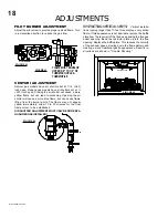
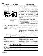
- check pressure readings:
Inlet pressure can be checked by turning screw (A) counter-clockwise
2 or 3 turns and then placing pressure gauge tubing over the test
point. Gauge should read 7" (minimum 4.5") water column for natural
gas or 13" (11" minimum) water column for propane. Check that main
burner is operating on "HI".
Outlet pressure can be checked the same as above using screw (B).
Gauge should read 3.5" water column for natural gas or 10" water
column for propane. Check that main burner is operating on "HI".
AFTER TAKING PRESSURE READINGS, BE SURE TO TURN
SCREWS CLOCKWISE FIRMLY TO RESEAL. DO NOT
OVERTORQUE.
Leak test with a soap and water solution.
Unit is over-fired or under-
fired.
P
I
A
B
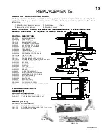
PILO
T
N
O
L
O
T
H I
LO
FF
O
Pilot goes out
while standing;
Main burner is in
'OFF' position.
Gas piping is undersized.
- turn on all gas appliances and see if pilot flame flutters, diminishes
or extinguishes, especially when main burner ignites. Monitor appli-
ance supply working pressure.
- check if supply piping size is to code. Correct all undersized piping.
Carbon is being
deposited on
glass, logs or com-
bustion chamber
surfaces.
Flame is impinging on the
logs or combustion cham-
ber.
- check that the logs are correctly positioned.
- open air shutter to increase the primary air.
- check the input rate: check the manifold pressure and orifice size
as specified by the rating plate values.
- check that the door gasketing is not broken or missing and that the
seal is tight.
- check that both 4" and 7" vent liners are free of holes and well
sealed at all joints.
Air shutter has become
blocked
- ensure air shutter opening is free of lint or other obstructions.
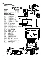
Summary of Contents for GD27 - N
Page 23: ...23 WS 415 090 04 03 00 NOTES...


