Napoleon GD27 - N Installation And Operation Instructions Manual Download Page 14

14

WS-415-090 / 04.03.00

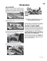
DOOR AND TRIM INSTALLATION:

 When re-install-

ing, retighten screws snugly. DO NOT OVER-TIGHTEN.

The top and bottom door tim may be installed next. Attach
magnets to the bottom door trim approximately 4" from
either end. Lift up the top trim and hook over the top of the
door. The bottom trim is inserted into the bottom door sill.
Push in to engage the magnets. Centre both side trims.

The louvre assemblies are
installed as illustrated in

FIGURES 31

.

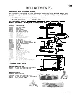
Optional plated door trim, door side trim, webbed facias,
arched door facias and bay door kits are available at your
local Napoleon / Wolf Steel dealer.

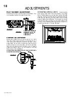
DOOR, LOUVRE AND TRIM REMOVAL

& INSTALLATION

Ensure that the door is properly clipped onto the steel
lip to prevent overheating, glass breakage and/or dis-
colouration of the upper trim.

DOOR REMOVAL:

 Both top and bottom door trim must

be removed prior to door removal. Lift up the top trim and
unhook from the door. The bottom trim may be pulled off
and lifted out of the bottom door sill.

Remove the five screws securing the sides and bottom of
the door. Lift up and out.

FIGURE 29

FIGURE 30

FIGURES 31

DOOR

STEEL LIP

Summary of Contents for GD27 - N

Page 1: ...nnot reach your gas supplier call the fire department LISTED DIRECT VENT MILLIVOL LISTED DIRECT VENT MILLIVOL LISTED DIRECT VENT MILLIVOL LISTED DIRECT VENT MILLIVOL LISTED DIRECT VENT MILLIVOLT T T T...

Page 2: ...should be located out of traffic and away from furniture and draperies Clothing or other flammable material should not be placed on or near the fireplace Any safety screen or guard removed for servic...

Page 3: ...ver requires the prior approval of an authorized company official Labour costs to the account of to the account of to the account of to the account of to the account of NAPOLEON NAPOLEON NAPOLEON NAPO...

Page 4: ...States The fireplace and its individual shutoff valve must be dis connected from the gas supply piping system during any pressure testing of that system at test pressures in ex cess of 1 2 psig 3 5 kP...

Page 5: ...When terminating vertically the vertical rise is a minimum 3 feet and a maximum 40 feet above the fireplace For safe and proper operation of the fireplace follow the ventinginstructionexactly Deviati...

Page 6: ...llow ing procedure for vent length calculations must be followed In an installation as shown in FIGURE 5 lengths A and C are known based on room height and roof re quirements Any 90 and 45 elbows must...

Page 7: ...ET Clearance above grade veranda porch deck or balcony Clearance to windows or doors that open Clearance to permanently closed windows Vertical clearance to ventilated soffit located above the termina...

Page 8: ...nded that For optimum performance it is recommended that For optimum performance it is recommended that all horizontal runs have a minimum inch rise all horizontal runs have a minimum inch rise all ho...

Page 9: ...e fireplace vent collar and secure with 3 8 screws 2 Using the 7 diameter flexible aluminum liner apply sealant slide a minimum of 2 over the fireplace combus tion air collar and secure with 3 8 screw...

Page 10: ...rminal and down to the caulk ing Tighten to ensure that a weather tight seal between the air terminal and the collar is achieved Attach the other storm collar centered between the air intake and the a...

Page 11: ...ons for Horizontal Air Terminal In stallations 2 Continue adding components alternating inner and outer venting Ensure that all 4 vent ing and elbows have sufficient vent spacers attached and each com...

Page 12: ...vary according to the mantle depth FIGURES 26 Use the graph to help evaluate the clearance needed MOBILE HOME INSTALLATION In Canada mobile home installation may be vented hori zontally or vertically...

Page 13: ...ROPERLY WILL CAUSE FLAMEIMPINGEMENTANDCARBONING Log colours may vary During the initial use of the fireplace the colours will become more uniform as colour pigments burn in during the heat activated c...

Page 14: ...S 31 Optional plated door trim door side trim webbed facias arched door facias and bay door kits are available at your local Napoleon Wolf Steel dealer DOOR LOUVRE AND TRIM REMOVAL INSTALLATION Ensure...

Page 15: ...E OFFSET FIGURE33 red white b l a c k FIGURE32 FIGURE37 RECEPTACLE THERMODISC GROUND SCREW JUNCTION BOX FIGURE36 Attach the connectors from the black and white wires to the thermodisc and secure the t...

Page 16: ...E FIGURE39 FIGURE38 FIGURE40 FIGURE41 ELECTRICAL INSTALLATION TO BE DONE BY A QUALI FIED INSTALLER and must be connected and grounded in accordance with local codes In the absence of local codes use t...

Page 17: ...RUCTIONS When lit for the first time the fireplace will emit a slight odour for a few hours This is a normal temporary condi tion caused by the curing of the logs and the burn in of internal paints an...

Page 18: ...ad to carboning Opening the air shutter will cause a more blue flame but can cause flame lifting from the burner ports The flame may not appear yellow immediately allow 15 to 30 minutes for the final...

Page 19: ...NO DESCRIPTION GD 225 36 BLACK DOOR FRAME WS 300 20 GLASS ONLY GD 010 402 GLASS c w GASKET GD 321 K BLACK DOOR C W GLASS GD 562 09 DOOR GASKET 100 INCHES WS 455 11 40 NATURAL GAS ORIFICE WS 455 033 5...

Page 20: ...3 TRIM KIT POLISHED BRASS GD3C 3 TRIM KIT CHROME GD6AB 6 TRIM KIT ANTIQUE BRASS GD6PB 6 TRIM KIT POLISHED BRASS GD6C 6 TRIM KIT CHROME GD43AB 4 3D TRIM KIT ANTIQUE BRASS GD43PB 4 3D TRIM KIT POLISHED...

Page 21: ...n around the thermocouple Pilot flame is not engulfing the thermocouple Thermocouple shorting faulty loosen and tighten thermocouple clean thermocouple and valve connection replace thermocouple replac...

Page 22: ...are very active Flames are con sistently too large or too small Carboning occurs check pressure readings Inlet pressure can be checked by turning screw A counter clockwise 2 or 3 turns and then placi...

Page 23: ...23 WS 415 090 04 03 00 NOTES...

Reviews: