background image

17

W415-0341 / F / 11.21.05

1. 

Move the fireplace into position. Measure the vent length

required between terminal and fireplace taking into ac-
count the additional length needed for the finished wall
surface and any 1¼" overlaps between venting compo-
nents.

2. 

Apply high temperature sealant to the outer edge of

the 4" inner collar of the fireplace.  Attach the first vent com-
ponent and secure using 3 self tapping screws. Repeat
using 7" piping.

3. 

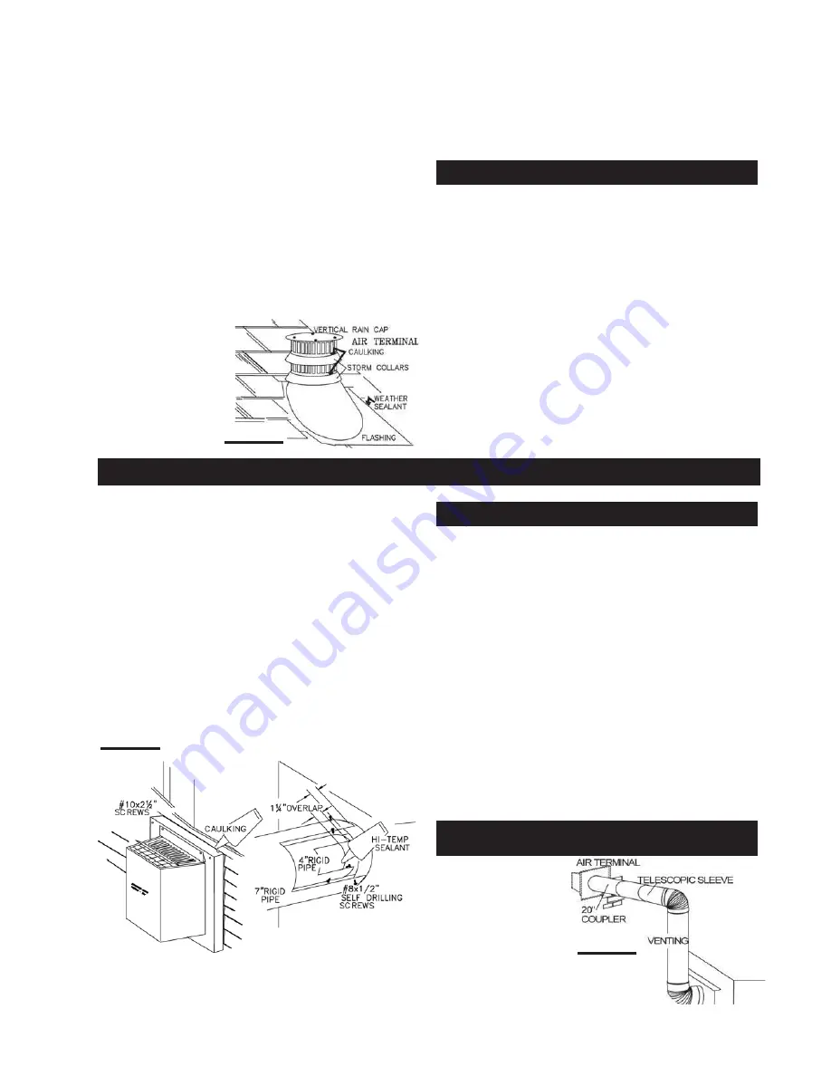
Holding the air terminal (lettering in an upright, read-

able position), insert into both vent pipes with a twisting
motion to ensure that both the terminal sleeves engage
into the vent pipes and the sealant. Secure the terminal to
the exterior wall and make weather tight by sealing with
caulking (not supplied).

The air terminal mounting plate may be recessed into
the exterior wall or siding by 1½", the depth of the return
flange.

A 45° corner installation
can have 0 inch rise
between the fireplace
combustion air collar
and the air terminal. 


In

this case, vent lengths
must be kept to a maxi-
mum of 24". For longer
vent lengths, a mini-
mum vertical rise of 24"
is required.

FIGURE 32

EXTENDED HORIZONTAL AND CORNER

AIR TERMINAL INSTALLATION

For safe and proper operation of the fire-

place, follow the venting instructions exactly.

For optimum performance, it is recommended that hori-
zontal runs have a minimum ¼ inch rise per foot  when
using Wolf Steel or Simpson Duravent rigid vent com-
ponents.

The vent system must be supported approximately every 3
feet for both vertical and horizontal runs.  Use Wolf Steel
vent spacers


W615-0033

 every 3 feet on either side of each

elbow to maintain the minimum 1¼" clearance between
the outer and inner vent pipes. Use Napoleon support ring
assembly 

W010-0370

 or equivalent noncombustible strap-

ping to maintain the minimum clearance to combustibles
for both vertical and horizontal runs.

FIGURE 31

5. 

Remove nails from the shingles, above and to the

sides of the chimney. Place the flashing over the air termi-
nal and slide it underneath the sides and upper edge of the
shingles. Ensure that the air terminal is properly centred
within the flashing, giving a 3/4" margin all around. Fasten
to the roof. Do 

not

 nail through the lower portion of the

flashing. Make weather-tight by sealing with caulking. Where
possible, cover the sides and top edges of the flashing
with roofing material.

6. 

Apply a heavy bead of weatherproof caulking 2 inches

above the flashing. Slide the storm collar around the air
terminal and down to the caulking. Tighten to ensure that a
weather-tight seal between the air terminal and the collar
is achieved. Attach the other storm collar centred between
the air intake and the air exhaust slots onto the air terminal.
Tighten securely. Attach the vertical rain cap.

Spacers are attached
to the 4" inner flex
liner at predetermined
intervals to maintain
a 1-1/4" air gap to the
7" outer liner. These
spacers must not be
removed.

7. 

If more liner needs to be used to reach the fireplace,

couple them together as illustrated. The vent system must be
supported approximately every 3 feet for both vertical and
horizontal runs. Use noncombustible strapping to maintain a
clearance to combustibles of 1".

1. 

Install the 4 inch diameter aluminium flexible liner to

the fireplace. Secure with 3 screws and flat washers. Seal
the joint and screw holes using the high temperature seal-
ant provided.

2. 

Install the 7 inch diameter aluminium flexible liner to

the fireplace. Attach and seal the joints.

FIREPLACE VENT CONNECTION

USING RIGID VENT COMPONENTS

HORIZONTAL AIR TERMINAL INSTALLATION

FIGURE 30

Summary of Contents for BGD33NR

Page 1: ...try to light any appliance Do not touch any electrical switch Do not use any phone in your build ing Immediately call your gas supplier from a neighbour s phone Follow the gas supplier s instructions...

Page 2: ...hing or other flammable material should not be placed on or near the fireplace Any safety screen or guard removed for servicing must be replaced prior to operating the fireplace It is imperative that...

Page 3: ...the prior approval of an authorized company official Labour costs to the account of the prior approval of an authorized company official Labour costs to the account of NAPOLEON NAPOLEON NAPOLEON NAPO...

Page 4: ...on and it is important to know the specifics that apply to your area for example in Massachusetts State The fireplace damper must be removed or welded in the open position prior to installation of a f...

Page 5: ...TERMINAL KIT GD222 VENTING LENGTHS AND AIR TERMINAL LOCATIONS VENTING The maximum allowable vertical vent length is 40 feet For optimum flame appearance and fireplace performance keep the vent length...

Page 6: ...r ignition Six 6 inches is the minimum bend radius allowed for the 7 diameter flexible liner For optimum performance it is recommended that horizontal runs have a minimum inch rise per foot when using...

Page 7: ...at open Clearance to permanently closed windows Vertical clearance to ventilated soffit located above the terminal within a horizontal distance of 2 feet from the centerline of the terminal Clearance...

Page 8: ...i cal rise to m a x i m u m of 40 feet vertical rise is equal to or greater than the horizontal run horizontal run verti cal rise to m a x i m u m of 40 feet vertical rise is equal to or greater than...

Page 9: ...ONS ELBOW VENT LENGTH VALUES Example 1 See graph to determine the required vertical rise VT for the required horizontal run HT For vent configurations requiring more than two 90 el bows the following...

Page 10: ...Formula 2 HT VT 24 75 feet 20 45 24 75 Since both formulas are met this vent configuration is ac ceptable FIGURE9 For vent configurations requiring more than two 90 elbows the following formulas appl...

Page 11: ...T VT Formula 2 HT VT 40 feet 90 90 Example 3 V1 3ft V2 8ft VT V1 V2 3 8 11 ft H1 2 5ft H2 2ft HR H1 H2 2 5 2 4 5 ft HO 03 three 90 elbows 90 03 270 90 5 4 ft HT HR HO 4 5 5 4 9 9 ft HT VT 9 9 11 20 9...

Page 12: ...raph to determine the required ver tical rise VT for the required horizontal run HT ceptable Example 5 V1 4ft V2 1 5ft VT V1 V2 4 1 5 5 5 ft H1 2ft H2 1ft H3 1ft H4 1 5ft HR H1 H2 H3 H4 2 1 1 1 5 5 5...

Page 13: ...03 90 90 90 90 5 4 ft HT HR HO 5 5 5 4 10 9 ft HT VT 10 9 15 25 9 ft Formula 1 HT VT 10 9 15 Formula 2 HT VT 40 feet 25 9 40 Since both formulas are met this vent configuration is ac ceptable FIGURE1...

Page 14: ...VT 3 x 4 5 13 5 ft 16 1 13 5 Since this formula is not met this vent configuration is unac ceptable Formula 2 HT VT 40 feet 20 6 40 Since only formula 2 is met this vent configuration is unac ceptable...

Page 15: ...e vent pipe collar down to cover up the open end of the shield and tighten This will prevent any materials such as insulation from filling up the 1 air space around the pipe For optimum performance it...

Page 16: ...ed length taking into account the additional length needed for the finished wall surface Slip the liner a mini mum of 2 over the inner sleeve of the air terminal and secure with 3 8 screws Apply a hea...

Page 17: ...Napoleon support ring assembly W010 0370 or equivalent noncombustible strap ping to maintain the minimum clearance to combustibles for both vertical and horizontal runs FIGURE31 5 Remove nails from th...

Page 18: ...eather tight by sealing with caulking Where possi ble cover the sides and top edges of the flashing with roof ing material 8 Apply a heavy bead of waterproof caulking 2 inches above the flashing Slide...

Page 19: ...IGURE37 GAS INSTALLATION MOBILE HOME INSTALLATION WIRE SIZE MAX LENGTH 14 gauge 100 feet 16 gauge 60 feet 18 gauge 40 feet FRAMING In Canada manufactured mobile home installation may be vented horizon...

Page 20: ...D33 GD34 BGD34 FIGURE39a d FIGURE40a d GD34 Finishing must be done using a non combustible material placed flush with the front face of the unit and extending from the top of the unit Example cement b...

Page 21: ...43 c Additional set screws may be installed TOP SLOT FINISHING MATERIAL CORNER POST NAILING TAB A B C CENTRE HOLE BGD33 NAILING TAB INSTALLATION It is best to frame your fireplace after it is position...

Page 22: ...ombustible materials must be installed flush with the front of the fireplace but must not cover any of the black face area of the fireplace Non combustible material brick stone or ceramic tile may pro...

Page 23: ...upport Position the top of the log into the pocket provided on the top of the rear log 1 Position the notch located in the bottom end of log 3 against the centre grate post Rest the top of log 3 into...

Page 24: ...entre grate post Rest the top of log 3 into the pocket at the top end of log 2 Place the bottom of log 4 onto the locating pin on the right side of the log support Rest the top into the pocket pro vid...

Page 25: ...he clips along the top of the louvre opening Secure using a screw through the centre slot NOTE Hood W335 0028 is re quired on B GD34 models Hood W335 0028 is recommended but not required on B GD33 mod...

Page 26: ...the fireplace base or the firebox Attach the connectors from the black and white wires to the thermodisc and secure the thermodisc bracket to the se curing stud at the bottom left of the unit using a...

Page 27: ...sult in a fire or explosion D Do not use this fireplace if any part has been under water Immediately call a qualified service technician to inspect the fireplace and replace any part of the control sy...

Page 28: ...mmable vapours and liquids The flow of combustion and ventilation air must not be obstructed 1 In order to properly clean the burner and pilot assembly remove the logs to expose both assemblies 2 Keep...

Page 29: ...PROPANE GAS VALVE 25 W010 0595 BURNER 29 W135 0082 LOG 5 CHARCOAL PIECE 30 W135 0182 LOG 6 23 W500 0096 FIRESTOP SPACER 32 W500 0208 RESTRICTOR PLATE ACCESSORIES FLEXIBLE VENT KITS TERMINAL KITS ROOF...

Page 30: ...30 W415 0341 F 11 21 05 NOTE SOME PARTS NOT EXACTLY AS SHOWN...

Page 31: ...ve replace Wall switch wiring is de fective disconnect switch wires from valve connect a jumper wire across terminals 1 3 if the main burner lights check the wires for de fects and or replace wires Pi...

Page 32: ...and 7 vent liners are free of holes and well sealed at all joints check that minimum rise per foor has been adhered to for any horizontal venting Air shutter has become blocked ensure air shutter open...

Reviews: