background image

ITEMS MA

Y NOT

 APPEAR EXACTL

AS ILLUSTRA

TED

FOR REPLACEMENTS P

AR

TS

REFER 

TO: 

"LIGHT

 ASSEMBL

Y"

SAFETY

 SCREEN


4

5


6


8


9


10


11


12


13


14


15

17

16

18

REF

. NO.

PART #

DESCRIPTION

ST

OCKED

1 2 3 4 5 6

7 8 9

REF

. NO.

DESCRIPTION

W135-0254

W135-0249

W135-0250 GL-651

W385-2010 W135-0580 W010-3295

W010-1379

PART #

11

15 16 17 18

10

W010-4177

W350-0342

W430-0013

W080-1786 W655-0239

W660-0009 W135-0257

W010-3685 W010-2020

W135-0232

14

12 13


7

FRONT

 CASTING

SAFETY

 SCREEN

DOOR ASSEMBL

Y

CONTROL

 COVER ASSEMBL

Y

BA

TTER

Y HOUSING

REAR LOG (GL-651)

LEFT

 LOG (GL-651)

RIGHT

 LOG  (GL-651)

LOG SET

NAPOLEON LOGO

DOOR CA

TCH MAGNET

 ASSEMBL

Y

MAGNET

 BRACKET

REAR LOG SUPPOR

ON/OFF SWITCH TOP

 CASTING

DOOR LA

TCHES (X2)

LIGHT

 ASSEMBL

Y

SIDE CASTING (X2)

1

2

3

X2

X2

ST

OCKED

YES YES

YES

YES

YES

YES

YES YES

YES

YES

11.1


OVER

VIEW

W415-2207 / A / 08.28.17

 43

EN

Summary of Contents for Bayfield GDS25N-1

Page 1: ...an aftermarket permanently located manufactured home USA only or mobile home where not prohibited by local codes This appliance is only for use with the type of gas indicated on the rating plate This...

Page 2: ...BARRIER INSTALLATION AND REMOVAL 26 5 3 GLASS DOOR INSTALLATION AND REMOVAL 27 5 4 LOG PLACEMENT 27 5 5 LOGO PLACEMENT 28 6 0 OPTIONAL BLOWER INSTALLATION 29 7 0 WIRING DIAGRAM 31 8 0 OPERATION 32 8...

Page 3: ...lower see OPTIONAL BLOWER INSTALLATION section Rating plate see RATING PLATE INFORMATION section Batteries must be disposed of according to the local laws and regulations Some batteries may be recycle...

Page 4: ...sh air If appliance keeps shutting off have it serviced Keep burner and control compartment clean Under no circumstances should this appliance be modified Do not allow wind or fans to blow directly in...

Page 5: ...sting of that system at test pressures in excess of 1 2 psig 35 mb The appliance must be isolated from the gas supply piping system by closing its individual manual shutoff valve during any pressure t...

Page 6: ...ertified high altitude input rating shall be reduced at the rate of 4 for each additional 1 000ft 305m Expansion contraction noises during heating up and cooling down cycles are normal and to be expec...

Page 7: ...ly Refer to the rating plate on the appliance for accurate information NOTE The rating plate must remain with the appliance at all times It must not be removed A barrier designed to reduce the risk of...

Page 8: ...ing Wolf Steel venting components use only approved Wolf Steel rigid flexible components with the following termination kits wall terminal kit GD 222 GD 222R or 1 12 to 7 12 pitch roof terminal kit GD...

Page 9: ...EGARDLESS OF HORIZONTAL VENT LENGTH 40FT 12m MAX 3FT 1m MIN The maximum horizontal run with a 57 1 45m vertical rise immediately above the appliance is 20 feet 6 1m 16 40 6cm 25 5 8 65 1cm 25 5 8 65 1...

Page 10: ...able vent length is 10 3 1m for a fireplace and 8 2 4m for a stove 8 2 3 1 SPECIAL VENT INSTALLATIONS 3 1 1 PERISCOPE TERMINATION 3 1 2 CORNER TERMINATION 12 305mm MIN TO GRADE BELOW GRADE INSTALLATIO...

Page 11: ...veranda porch deck or balcony N 16 40 6cm 16 40 6cm Clearance above the roof O 2 0 6m 2 0 6m Clearance from an adjacent wall including neighbouring buildings P 8 2 4m 8 2 4m Roof must be non combusti...

Page 12: ...for 45 exit only 3 4 ELBOW VENT LENGTH VALUES 3 3 DEFINITIONS 11 1 For the following symbols used in the venting calculations and examples are greater than equal to or greater than less than equal to...

Page 13: ...4m HO 03 one 45 elbow two 90 elbows 135 03 225 135 2 7 FT 0 8m HT HR HO 4 5 FT 1 4m 2 7 FT 0 8m 7 2 FT 2 2m HT VT 7 2 FT 2 2m 8 FT 2 4m 15 2 FT 4 6m Formula 1 HT VT 7 2 FT 2 2m 8 FT 2 4m Formula 2 HT...

Page 14: ...VT 4 2 FT 1 3m x 5 5 FT 1 7m 23 1 FT 7m 13 6 FT 4 2m 23 1 FT 7M Formula 2 HT VT 24 75 FT 7 5m 19 1 FT 5 8m 24 75 FT 7 5m Since both formulas are met this vent configuration is acceptable 90 90 45 V1...

Page 15: ...10 FT 3 1m 15 FT 4 6m H1 3 FT 0 9m H2 2 5 FT 0 8m HR H1 H2 3FT 0 9m 2 5FT 0 8m 5 5 FT 1 7m HO 03 one 45 three 90 elbows 135 03 45 270 135 5 4 FT 1 6m HT HR HO 5 5 FT 1 7m 5 4 FT 1 m 10 9 FT 3 3m HT V...

Page 16: ...4m 5 4FT 1 6m 13 4FT 4 1m HT VT 13 4FT 4 1m 2 5FT 0 8m 15 9FT 4 8m Formula 1 HT 3VT 3VT 3FT 0 9m x 2 5FT 0 8m 7 5FT 2 3m 13 4 FT 4 1m 7 5 FT 2 3m Since this formula is not met this vent configuration...

Page 17: ...quired directly off the appliance Follow vent manufacturer s installation instructions Different manufacturer s venting components must not be combined Once the preferred manufacturer s appliance adap...

Page 18: ...3 SCREWS MUST ALSO BE USED TO ENSURE THE CONNECTION CANNOT SLIP OFF DO NOT CLAMP THE FLEXIBLE VENT PIPE RISK OF FIRE EXPLOSION OR ASPHYXIATION IMPROPER SUPPORT OF THE ENTIRE VENTING SYSTEM MAY ALLOW V...

Page 19: ...ver up the open end of the shield and tighten This will prevent any materials such as insulation from filling up the 1 25mm air space around the pipe FIRESTOP UNDERSIDE OF JOIST CAULKING VENT PIPE SHI...

Page 20: ...wall or siding no greater than the depth of its return flange 18 1 Screws Supplied 2 50 8mm Overlap Outer Flex Pipe Inner Flex Pipe Red RTV Silicone Caulking Screws Supplied 2 50 8mm Overlap Outer Fl...

Page 21: ...g over the air terminal connector leaving a min 3 4 19mm of the air terminal connector showing above the top of the flashing Slide the flashing underneath the sides and upper edge of the shingles Ensu...

Page 22: ...anada or to the current National Fuel Gas Code ANSI Z223 1 NFPA 54 in the United States D When flexing any gas line support the gas valve so that the lines are not bent or kinked E The gas line flex c...

Page 23: ...opriate securing kit For mobile home installations the appliance must be fastened in place It is recommended that the appliance be secured in all installations Always turn off the pilot and the fuel s...

Page 24: ...apoleon appliance is in the centre of a building thereby allowing the most ef cient use of the heat created The location of windows doors and the traf c ow in the room where the appliance is to be loc...

Page 25: ...WITH THESE INSTRUCTIONS MAY CAUSE A FIRE OR CAUSE THE APPLIANCE TO OVERHEAT ENSURE ALL CLEARANCES I E BACK SIDE TOP VENT HEARTH MANTEL FRONT ETC ARE CLEARLY MAINTAINED WARNING W415 1332 A 11 21 14 25...

Page 26: ...o scratch the bottom casting D Reverse these steps to remove WARNING GLASS MAY BE HOT DO NOT TOUCH GLASS UNTIL COOLED 5 0 FINISHING 5 1 CAST FRONT INSTALLATION AND REMOVAL A Remove safety barrier B Li...

Page 27: ...EWS BRACKET It is not necessary to remove the cast front however this will make for a more simple log installation In order to assemble the log set the glass door must be removed see CAST FRONT GLASS...

Page 28: ...front of and against the right end of log 2 D Reinstall the glass door front 5 6 LOGO PLACEMENT 5 5 1 SWITCH FUNCTIONS W415 1332 A 11 21 14 Remove the backing from the logo and position onto the contr...

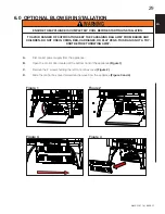
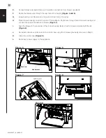
Page 29: ...S BED CARRIAGES OR PLAY PENS THIS BAG IS NOT A TOY KNOT BEFORE THROWING AWAY A Disconnect power supply from the appliance B Open the control door located at the bottom front of the appliance Figure 1...

Page 30: ...o rear hole of housing H Place blower housing close to the rear of the appliance Route wire through hole in blower housing and connect the spade connectors to blower Figure 7 I Align the blower to the...

Page 31: ...ng plug for protection against shock hazard and should be connected into a properly grounded circuit Do not cut or remove the grounding prong from the plug This appliance must be electrically connecte...

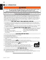
Page 32: ...the access panel G Wait five 5 minutes to clear out any gas If you smell gas including near the floor STOP Follow B in the above safety information on this label If you don t smell gas go to the next...

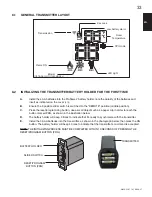
Page 33: ...as shown in the illustration below D The battery holder will beep 3 times to indicate that it s ready to synchronize with the transmitter E Install the 3 AAA batteries into the transmitter as shown in...

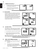
Page 34: ...F 76 F Hi FLAME OFF FLAME AT LEVEL 1 FLAME AT LEVEL 5 FLAME AT HI LEVEL 6 35 8A If the appliance is equipped with a hot air circulating fan the speed of the fan can be controlled by the remote system...

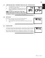
Page 35: ...egardless of what is set on the remote control handset 35 22 76 F IPI 76 F CPI This function will lock the keys to avoid unsupervised operation A Press the MODE and UP keys at the same time B To de ac...

Page 36: ...ow no beep will be emitted from the receiver when it receives an ON OFF command This in an alert for the receiver that there s low battery When the batteries are replaced the beep will be emitted from...

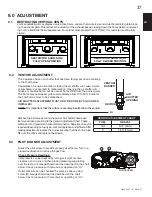
Page 37: ...TRICTOR SHOWN IN A FULLY OPEN POSITION RESTRICTOR SHOWN IN A FULLY CLOSED POSITION Vertical installations may display a very active flame Loosen the two screws and slide the restrictor plate block ing...

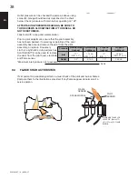
Page 38: ...on Prior to pilot adjustment ensure that the pilot assembly has not been painted If overspray or painting of the pilot assembly has occurred remove the paint from the pilot assembly or replace Fine em...

Page 39: ...ue to excessive lint dust from carpeting pets etc simply vacuum using the brush attachment 6 If your appliance is equipped with relief doors ensure the system performs effectively Check that the gaske...

Page 40: ...gently remove any build up on the pilot assembly including if equipped thermopile thermocouple flame sensor and igniter NOTE Clean flame sensor using a fine emery cloth or a synthetic scrub pad such a...

Page 41: ...ASSEMBLY This must be carried out by anAUTHORIZED REPRESENTATIVE OF WOLF STEEL LTD or a QUALIFIED GAS INSTALLER in accordance with local codes or in the absence of local codes with the requirements o...

Page 42: ...vec l appareil et sera install pour la protection des enfants et d autres personnes risque LA VITRE CHAUDE CAUSERA DES BR LURES NE PAS TOUCHER LA VITRE AVANT QU ELLE AIT REFROIDI NE JAMAIS LAISSER LES...

Page 43: ...7 18 10 W010 4177 W350 0342 W430 0013 W080 1786 W655 0239 W660 0009 W135 0257 W010 3685 W010 2020 W135 0232 14 12 13 7 FRONT CASTING SAFETY SCREEN DOOR ASSEMBLY CONTROL COVER ASSEMBLY BATTERY HOUSING...

Page 44: ...R 14 W725 0057 VALVE P 17 18 PRO 2 WIRE HARNESS W750 0276 W750 0412 BLOWER LIGHT WIRE HARNESS BATTERY HOUSING WIRE HARNESS W750 0268 6 7 7 0 W660 0126 SER PRO 2 TRANSMITTER 10 W432 0078 3 8 MANIFOLD 1...

Page 45: ...TONE BRICK PANEL GDS813KT 4 W090 0135 LS PORCELAIN PANEL PRP25 5 W090 0133 REAR PORCELAIN PANEL PRP25 6 W090 0134 RS PORCELAIN PANEL PRP25 7 8 GSB25KT BLOWER KIT GDSLL KT LEG LEVELING STOVE SECURING K...

Page 46: ...s into the module Remove and verify continuity of each wire in wiring harness Module is not grounded Verify the valve and pilot assemblies are properly grounded to the metal chassis of the appliance o...

Page 47: ...iring Connection Inspect all wires ensure good tight connections Verify that all wiring is installed exactly as specified Wiring harness Inspect the wiring harness and verify the harness is tightly co...

Page 48: ...ds of dampness condensation damaging chemicals or cleaners will not be the responsibility of NAPOLEON All parts replaced under the President s Limited Lifetime Warranty Policy are subject to a single...

Page 49: ...28 1 15 0 SERVICE HISTORY W415 2207 A 08 28 17 49 EN...

Page 50: ...rie Ontario Canada L4M 0G8 214 Bayview Drive Barrie Ontario Canada L4N 4Y8 103 Miller Drive Crittenden Kentucky USA 41030 7200 Trans Canada Highway Montreal Quebec Canada H4T 1A3 NAPOLEON CELEBRATING...

Page 51: ...avec le type de gaz indiqu sur la plaque d homologation Cet appareil ne peut tre converti d autres gaz sauf si une trousse de conversion est utilis e Si ces instructions ne sont pas suivies la lettre...

Page 52: ...E PROTECTION 76 5 3 INSTALLATION ET ENL VEMENT DE LA PORTE VITR E 77 5 4 DISPOSITION DES B CHES 77 5 5 MISE EN PLACE DU LOGO 78 6 0 INSTALLATION DE LA SOUFFLERIE OPTIONNELLE 79 7 0 SCH MA DE C BLAGE 8...

Page 53: ...ans votre centre de recyclage local Rensei gnez vous aupr s de votre municipalit au sujet des directives de recyclage Las bater as deben desecharse de acuerdo con las leyes y regulaciones locales Algu...

Page 54: ...inflammables Si l appareil s teint n allume pas l appareil jusqu ce que vous donner de l air frais Si l appareil continue de s teindre faire r parer Garder propres le br leur et le compartiment de co...

Page 55: ...es maisons mobiles quip es au gaz CAN CSA Z240 S RIE MM au Canada ou selon les normes ANSI Z223 1 et NFPA 54 aux tats Unis L alimentation de gaz de l appareil doit tre d branch e pendant les essais de...

Page 56: ...duit au taux de 4 pour chaque 1 000 pieds 305m suppl mentaires Les bruits caus s par l expansion et la contraction lors des cycles de chauffage et de refroidissement sont tout fait normaux et il faut...

Page 57: ...catif seulement Pour les renseignements exacts consultez la plaque d homologation fi x e sur l appareil NOTE Le plaque d homologation doit rester avec l appareil tout le temps Il ne doit pas tre enlev...

Page 58: ...ment avec les ensembles de terminaison suivants les ensembles de terminaison murale GD222 GD222R ou l ensemble de terminaison pour toit de pente 1 12 7 12 GD110 l ensemble de terminaison pour toit de...

Page 59: ...UR DE LA COURSE HORIZONTALE 40PI 12m MAX 3FT 1m MIN Lorsque la course verticale imm diatement la sortie de l appareil est de 57 1 45m alors la course hori zontale maximale est de 20 pieds 6m 16 40 6cm...

Page 60: ...un foyer et 8 pieds 2 4m pour un po le 8 2 3 1 INSTALLATIONS PARTICULI RES D VENTS 3 1 1 ENSEMBLE P RISCOPIQUE 3 1 2 TERMINAISON EN COIN 12 305mm MINIMUM AU NIVEAU DU SOL INSTALLATION SOUS LE NIVEAU D...

Page 61: ...adjacents incluant les maisons voisines P 8 2 4m 8 2 4m Le toit doit tre incombustible et sans ouvertures Q 3 0 9m 3 0 9m Voir le tableau pour les dimensions d un mur plus large R 6 1 8m 6 1 8m Voir l...

Page 62: ...RS D VENT 3 3 L GENDE 11 1 Les symboles suivants sont utilis s dans le calcul et les exemples d vacuation plus grand que plus grand ou gal plus petit que plus petit ou gal HT total de la longueur des...

Page 63: ...eptables pour HT et VT Lorsque la configuration de l vacuation exige plus qu un coude de 45 et de 90 les formules suivantes s appliquent Formule 1 HT VT Formule 2 HT VT 40 pieds 12 2m Exemple V1 8 PI...

Page 64: ...PI 7m Formule 2 HT VT 24 75 PI 7 5m 19 1 PI 5 8m 24 75 PI 7 5m Puisque les deux formules sont respect es cette configuration d vacuation est acceptable H4 90 90 45 V1 H1 H2 COURSE VERTICALE REQUISE EN...

Page 65: ...on de l vacuation exige plus qu un coude de 45 et un coude de 90 les formules suivantes s appliquent Formule 1 HT VT Formule 2 HT VT 40 pieds 12 2m Exemple V1 5 PI 1 5m V2 10 PI 3 1m VT V1 V2 5 PI 1 5...

Page 66: ...PI 2 4m 5 4 PI 1 6m 13 4 PI 4 1m HT VT 13 4 PI 4 1m 2 5 PI 0 8m 15 9 PI 4 8m Formule 1 HT 3VT 3VT 3PI 0 9m x 2 5PI 0 8m 7 5PI 2 3m 13 4PI 4 1m 7 5PI 2 3m Puisque cette formule n est pas respect e cett...

Page 67: ...l Suivez les instructions d installation du fabricant du syst me d vacuation Des composants d vacuation de diff rents fabricants ne doivent pas tre combin s Une fois que l adaptateur de votre choix es...

Page 68: ...AUSSI INSTALLER TROIS VIS POUR VOUS ASSURER QUE LE RACCORDEMENT NE SE D FASSE PAS NE SERREZ PAS LA GAINE FLEXIBLE RISQUE D INCENDIE D EXPLOSION OU D ASPHYXIE SI L ENSEMBLE DU SYST ME DE CONDUIT D VEN...

Page 69: ...d vacuation et l espaceur coupe feu C Dans le grenier faites glisser le collet de conduit d vacuation vers le bas afin de recouvrir l extr mit ouverte du protecteur de conduit d vacuation et serrez Ce...

Page 70: ...1 Vis Vis Fournies 2 50 8mm Chevauchement Gaine flexible ext rieure int rieure Scellant haute temp rature Calfeutrage Scellant haute temp rature Vis Bague d accouplement int rieur et ext rieur Gaine f...

Page 71: ...par dessus le connecteur de terminaison en laissant un minimum de 3 4 19 1mm de connecteur de terminaison visible au dessus du haut du solin Glissez le solin sous les c t s et le bord sup rieur des b...

Page 72: ...absence de codes locaux l installation doit tre conforme au Code d installation du gaz CAN CSA B149 1 dans sa version pour le Canada ou le National Fuel Gas Code ANSI Z223 1 NFPA 54 pour les tats Uni...

Page 73: ...ributeur permettant la s curisation kit Lors d une installation dans une maison mobile l appareil doit tre fix au plancher teignez toujours la veilleuse et l alimentation en gaz la source avant de d p...

Page 74: ...s et la circulation dans la pi ce o se trouve l appareil devront tre pris en consid ration Si possible vous devriez choisir un emplacement o le syst me d vacuation peut passer travers la maison sans a...

Page 75: ...PECTER CES INSTRUCTIONS PEUT CAUSER UN INCENDIE OU UNE SUR CHAUFFE ASSUREZ VOUS QUE TOUS LES D GAGEMENTS C D ARRI RE C T S DESSUS VENTS TABLETTE FA ADE ETC SONT RESPECT S LA LETTRE AVERTISSEMENT AVERT...

Page 76: ...cran de protection et enfoncez sur de l appareil Attention ne pas rayer lacoul e de fond WARNING GLASS MAY BE HOT DO NOT TOUCH GLASS UNTIL COOLED 5 0 FINISHING 5 1 CAST FRONT INSTALLATION AND REMOVAL...

Page 77: ...n cessaire de retirer la fa ade en fonte cependant cela facilitera l installation des b ches Pour installer les b ches la porte vitr e doit tre enlev e Voir la section INSTALLATION ET ENL VEMENT DE L...

Page 78: ...the right end of log 2 D Reinstall the glass door front 5 6 LOGO PLACEMENT 5 5 1 SWITCH FUNCTIONS W415 1332 A 11 21 14 Retirez le papier dorsal et positionnez le logo sur la porte de commande tel qu...

Page 79: ...ES POUSSETTES OU LES PARCS DE JEU CE SAC N EST PAS UN JOUET NOUEZ LE AVANT DE LE JETER A D branchez l alimentation lectrique de l appareil B Ouvrez la porte de contr le situ e au bas l avant de l appa...

Page 80: ...rectangulaires et le fil de mise la terre Figure 7 H Alignez la soufflerie avec l arri re du bo tier de contr le et fixez la avec les deux vis fournies dans l ensemble Figure 8 I R installez le couve...

Page 81: ...ILISATEUR VEILLEUSE LECTRONIQUE SOUPAPE LECTRONIQUE Cet appareil doit tre raccord lectriquement et mis la terre conform ment aux codes locaux En l absence de codes locaux utilisez la version courante...

Page 82: ...tez les piles dans l metteur 11 Appuyez sur le bouton ON de la t l commande Vous devriez entendre un bip du r cepteur vous indiquant que la communication est bonne Pour activer le r cepteur r f rez vo...

Page 83: ...le couvercle B Assurez vous que le commutateur glissi re est plac la position REMOTE position centrale C Appuyez sur le bouton r initialisation programmation utilisez un objet de petite taille comme...

Page 84: ...ce 35 5A 73 F 23 C 8 3 AFFICHER DE TEMP RATURE 8 4 HAUTEUR DE LA FLAMME Si l appareil est muni d une soufflerie la vitesse de celle ci peut tre contr l e par le syst me de t l commande La soufflerie c...

Page 85: ...t l commande 35 22 76 F IPI 76 F CPI 76 F IPI 76 F CPI 8 8 FONCTION DE S CURIT POUR ENFANTS Cette fonction verrouillera les touches pour emp cher une utilisation non supervis e A Appuyez simultan ment...

Page 86: ...es du r cepteur sont faibles celui ci n mettra pas de bip lorsqu il recevra une commande MARCHE ARR T Ceci est pour vous signaler que les piles du r cepteur sont faibles Lorsque les piles sont remplac...

Page 87: ...ser la plaque de restriction bloquant le chemin d chappement Ceci r duit la vitesse des gaz d chappement ralen tissant le mod le de flamme et cr ant un aspect de flamme plus traditionnel Pour les vent...

Page 88: ...ge de la veilleuse ou remplacez le Une toile d meri ou un tampon r curage comme Scrotch Brite peut tre utilis pour enlever la peinture sur la hotte de la veilleuse sur l lectrode et sur le capteur de...

Page 89: ...protection le nettoyage peut tre n cessaire en raison d un exc s de poussi re peluches des tapis animaux etc utilisez un l attachement du brosse sur aspirateur pour nettoyer l cran 6 Si votre appareil...

Page 90: ...la veilleuse et aussi s il y a lieu sur la thermopile le thermocouple le capteur de flamme et l allumeur REMARQUE Vous devrez nettoyer le capteur de amme l aide d une morceau de de laine d acier ou un...

Page 91: ...with the requirements of the provincial state authorities having jurisdiction and in accordance with the requirements of the CAN1 B149 Installation Code in Canada and theANSI Z223 1 National Fuel Gas...

Page 92: ...SSEMENT 10 5 SOINS DES PI CES PLAQU ES 6 1 Si l appareil est muni de pi ces plaqu es vous devez enlever toutes traces de doigts ou autres marques des surfaces plaqu es avant d allumer l appareil pour...

Page 93: ...50 0342 W430 0013 W080 1786 W655 0239 W660 0009 W135 0257 W010 3685 W010 2020 W135 0232 14 12 13 7 FA ADE EN FONTE L CRAN DE PROTECTION ASSEMBLAGE DE LA PORTE L ASSEMBLAGE DU COUVRE DE CONTR LE BO TIE...

Page 94: ...UPAPE P 17 18 HARNAIS DE FILS PRO 2 W750 0276 W750 0412 HARNAIS DE FILS DE SOUFFLERIE LUMI RE HARNAIS DE FILS DU BO TIER DE PILES W750 0268 6 7 7 0 W660 0126 SER T L COMMANDE PRO 2 10 W432 0078 COLLEC...

Page 95: ...CELAINE DU C T DROITE PRP25 7 8 GSB25KT SOUFFLERIE GDSLL KT TROUSSE POUR MISE DE NIVEAU FIXATION DE L APPAREIL 1 A stone inset can be cut to enhance the cast top and to match the room d cor A template...

Page 96: ...la veilleuse et de la soupape sont bien mis la terre au niveau du ch ssis m tallique de l appareil ou de l ensemble de b ches tincelle la veilleuse mais celle ci ne s allume pas Alimentation en gaz V...

Page 97: ...nnexions sont bien serr es V rifiez si tout le filage est install exactement tel que sp cifi Harnais de fils Inspectez le harnais de fils et v rifiez qu il soit solidement branch au module V rifiez qu...

Page 98: ...limit e du Pr sident ne peuvent faire l objet que d une seule r clamation Durant les dix premi res ann es NAPOL ON remplacera ou r parera les pi ces d fectueuses qui sont couvertes par la garantie vi...

Page 99: ...liers Travail effectu Nom du technicien D taillant Historique d entretien de l appareil Cet appareil doit tre entretenu annuellement selon son usage Date 15 0 HISTORIQUE D ENTRETIEN DE L APPAREIL FR W...

Page 100: ...r al Qu bec H4T 1A3 24 Napoleon Road Barrie Ontario Canada L4M 0G8 214 Bayview Drive Barrie Ontario Canada L4N 4Y8 103 Miller Drive Crittenden Kentucky USA 41030 NAPOL ON C L BRE PLUS DE 40 ANS D EXIS...

Reviews: