8 .
(4)
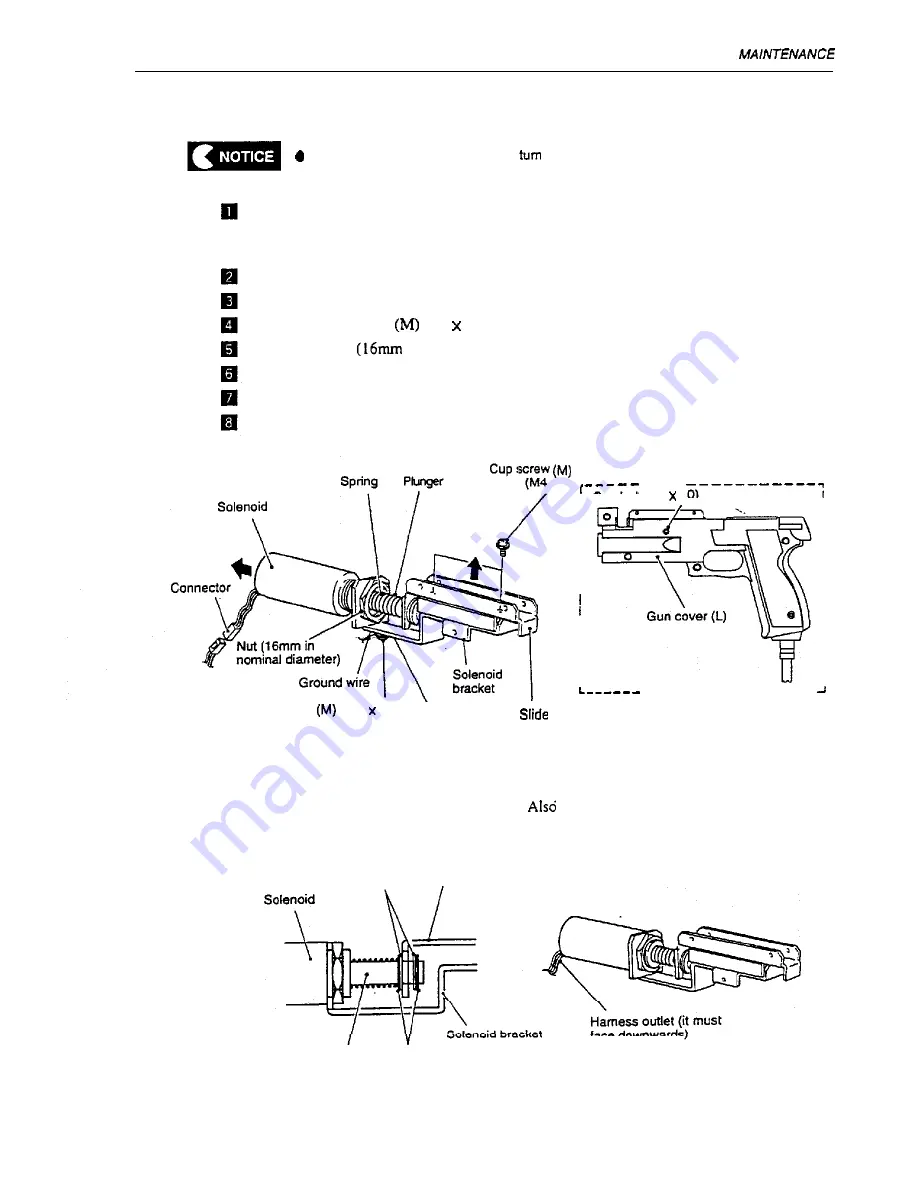
Replacing the solenoid with a new one
Before carrying out this task, always
off the power switch to protect the electric
circuit from damage.
Detach
the gun cover and gun slide.
(See P-69.8-3-5 (2) “How
to Open the Gun Slide” and P-70.8-3-5 (3) “How to Open the
G u n C o v e r . “ )
Disconnect the connectors of the solenoid.
Remove the cap bolt (M3 x 10) on the gun cover(L) and detach the solenoid bracket.
Remove the cup screw
(M3 8) and detach the
ground wire.
Loosen the nuts
in nominal diameter) fixing the solenoid.
Pull out the solenoid.
Remove the two cup screws (M) (M4 x 6) and detach the slide guide.
Pull out the solenoid plunger. At that time, take care not to lose the spring.
x6)
____
, Cap bolt (M3 10)
I
I
I
I
I
I
I
I
I
I
I
I
I
I
I
I
I
I
I
I
I
I
I
I
I
I
I
I
,
I
_ _ _ _ _ _ _ _ - - - - - - - -
Cup screw
(M3
6)
Toothed
washer
guide
q
Attach the components in reverse order. At that time. match the D-type hole of the sole-
noid
bracket to the D shape of the solenoid.
pay attention to the order to attach the
E-type snap rings and spacers.
Spacers
Slide guide
face downwards)
Plunger
E-type snap rings
7 1
Summary of Contents for TIME CRISIS 2
Page 1: ...__...
Page 76: ...10 PARTS L ST 10 PARTS LIST 1 O l Cabinet Assy...
Page 78: ...10 PARTS L ST 1 O 2 Signboard Assy 7 6...
Page 80: ...10 PARTS LIST 1 O 3 Control base Assy K I 1 c c 53 x3 0 1 78...
Page 81: ...10 PARTSLET 79...
Page 82: ...10 PARTS LIST 1 O 4 Rack Assy 0 c 0 cl cl...
Page 84: ...10 PARTS UST 10 5 Cord box Assy 6 _ r l 63 8 I I l L L J mm e...
Page 86: ...10 PARTS LIST 10 6 Tower Assy c3 cl zd 8 4...
Page 88: ...10 PARTS LIST 10 7 Pedal Assy 6 6...
Page 90: ...10 PARTS LIST 1 O 8 Gun Assy...
Page 92: ...10 PARTS LET 1 O 9 Coin Assy B 90...
Page 94: ...10 PARTS L ST 92...
Page 95: ...1 j i 1 i 1 i I 0 M I...
Page 96: ...11 Wiring Diagrah _ _ ____ __ _ _ ___ I I coin Assy j L _ _ _ EL I T o w e r Qsy 1...


