background image

12 

WWW

.N

AKAYAMA

T

OOLS

.

COM


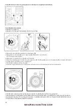
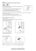
Remove the spring clip 

(3)

.


Remove the rope rotor with washer 

(4) 

and pawl 

(5)

. Ease the cap (6) out 

of the starter grip.


Remove remaining rope from the rotor and grip.


Tie a simple overhand knot in the end of the new starter rope (see Specifications) and then thread the rope through 

the top of the grip and the rope bush 

(7)

.


Refit the cap in the grip.


Thread the rope through the rotor and secure it in the rotor with a simple overhand knot.


Fit the pawl (5) in the rotor and slip the washer (4) over the starter post. 


Use a screwdriver or suitable pliers to install the spring clip (3) on starter post and over the peg on the pawl-the spring clip 

must point clock wise - see illustration. Go to "Tensioning rewind spring". 


Replacing a broken rewind spring 


Lubricate the new spring with a few drops of non-resinous oil. Remove the rope rotor as described in "Replacing the starter 

rope". Remove parts of old spring. 


Fit new spring housing - bottom plate must face downward. Engage outer spring loop over the lug. Refit the rope rotor. 

Go to "Tensioning rewind spring". 


If the spring pops out and uncoils during installation: Refit it in the spring housing in the counter- clockwise direction - start 

outside and work inward. 


Summary of Contents for BL4300

Page 1: ...BL4300 Owner s manual Art Nr 023456 WWW NAKAYAMATOOLS COM...

Page 2: ...2 WWW NAKAYAMATOOLS COM GR 1 2...

Page 3: ...3 WWW NAKAYAMATOOLS COM...

Page 4: ...4 WWW NAKAYAMATOOLS COM OFF 3 10...

Page 5: ...5 WWW NAKAYAMATOOLS COM Service OFF ON...

Page 6: ...6 WWW NAKAYAMATOOLS COM 90 Premium...

Page 7: ...7 WWW NAKAYAMATOOLS COM TC H 1 2 TC 25 1...

Page 8: ...8 WWW NAKAYAMATOOLS COM 1 ON 2...

Page 9: ...9 WWW NAKAYAMATOOLS COM 2 1 OFF OFF ON 5 15...

Page 10: ...10 WWW NAKAYAMATOOLS COM 1 2 H L 1 4 H L LA L LA...

Page 11: ...11 WWW NAKAYAMATOOLS COM LA L H H 1 4 A 100 1 2 3 Service...

Page 12: ...12 WWW NAKAYAMATOOLS COM 1 2 3 4 5 6 7 5 4 3...

Page 13: ...13 WWW NAKAYAMATOOLS COM OFF 3 UV 43cc 1 7hp 12m3 min 4200m3 min 1 2L Service...

Page 14: ...14 WWW NAKAYAMATOOLS COM 12 x x x x x x x x x x x x x x x x x x x x x Service x...

Page 15: ...15 WWW NAKAYAMATOOLS COM Service...

Page 16: ...al models with different features Components that are not installed in all models and related applications are marked thus Such components are available as special accessories from your dealer Enginee...

Page 17: ...of chrome leather Always shut off the engine before refuelling Gasoline is an extremely flammable fuel Do not smoke or bring any fire or flame near the fuel Do not fuel a hot engine fuel may spill and...

Page 18: ...a firm and secure footing Examine the work area Do not direct the air blast towards bystanders since the air flow can blow small objects at great speed Take care in slippery conditions On ice in wet o...

Page 19: ...ments Always clean dust and dirt off the machine after finishing work Do not service or store your unit near any fire or flame Check fuel cap regularly for leaks Use only an approved spark plug see Sp...

Page 20: ...tably against your back Unsuitable fuels or lubricants or mix ratios other than those specified may result in serious damage to the engine piston seizure rapid rate of wear etc Gasoline Use only regul...

Page 21: ...the filler cap and the area around it to ensure that no dirt falls into the tank Position the unit so that the filler cap is facing up Take care not to spill fuel while fuelling and do not overfill t...

Page 22: ...lear of the general work area and the nozzle Make sure you have a firm footing Hold the unit with your left hand on the housing and put one foot against the base plate to prevent it slipping Pull the...

Page 23: ...Now start the engine Fuel tank run until dry and then refuelled Pull the starter rope several times to prime the fuel line Operating instructions During break in period A factory new machine should n...

Page 24: ...adjusting screws down onto their seats clockwise Open the high speed screw H one full turn Open the low speed screw L one full turn Adjusting idle Speed Engine stops while idling Carry out standard s...

Page 25: ...park plug comes with a detachable adapter nut 1 screw it on firmly On all Spark Plugs Always press the boot 2 firmly on to the spark plug 3 Engine Running Behaviour If engine running behavior is unsat...

Page 26: ...over the starter post Use a screwdriver or suitable pliers to install the spring clip 3 on starter post and over the peg on the pawl the spring clip must point clock wise see illustration Go to Tensio...

Page 27: ...ine in a dry high or locked location out of the reach of children and other unauthorized persons Do not expose the container to direct sunlight for unnecessarily long periods UV rays can make the cont...

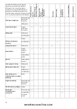
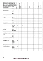
Page 28: ...aged if required Complete machine Visual inspection condition leaks x x Clean x Control handle Check operation x x Air filter Clean x Replace Filter in fuel tank Check x Replace x x fuel tank Clean x...

Page 29: ...ular basis If these maintenance operations cannot be performed by the owner they should be performed by an authorized servicing dealer If these operations are not carried out as specified the user ass...

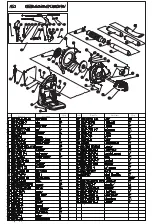
Page 30: ...Ser No Part No Part Name Qty Ser No Part No Part Name Qty...

Page 31: ...Ser No Part No Part Name Qty Ser No Part No Part Name Qty...

Reviews: