


A52
SINGLE DUCT TERMINAL UNITS
A
6-18-20
SINGLE DUCT TERMINAL UNITS • 3000 SERIES
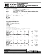
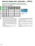
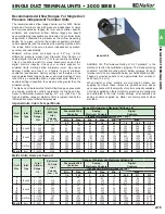
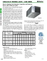
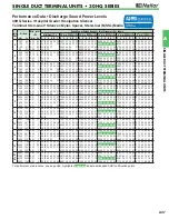
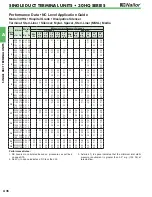
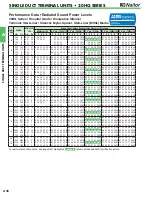
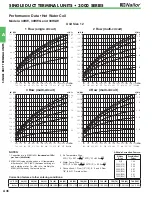
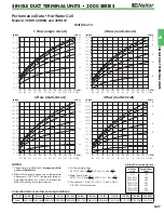
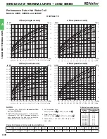
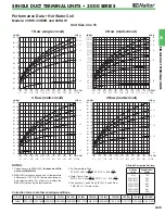
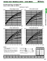
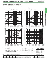
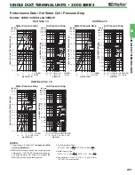
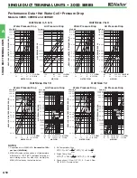
Electric Heating Coils Selection, Capacities and Features
Models: 30RE, 30REQ and 30HQE
Nailor manufactures its own electric heating coils. They have
been specifically designed and tested for use with variable air
volume single duct terminal units.
All terminals with electric heat have been tested and ETL listed
as an assembly, eliminating the need to mount coils a minimum
of 36" (914) downstream or having to ship a bulky length of
ductwork when coils are to be supplied mounted on the terminal.
Nailor electric coils are factory mounted as an integral part
of the terminal unit in an insulated extended plenum section.
Total length of the casing including heater terminal is only 31"
(787), providing a compact, easy to handle unit. The unique
inclined opposed blade damper design provides improved
and more even airflow over the coil elements compared with
round butterfly damper designs, which helps to minimize air
stratification, avoid nuisance tripping of the thermal cut-outs and
maximize heat transfer.
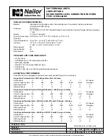
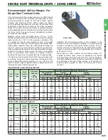
Selection Guidelines:
The table below provides a general guideline as to the voltages
and maximum kiloWatts available for each terminal unit size.
Up to three stages of heat are available. A minimum of 0.5 kW/
stage is required.
For optimum diffuser performance and maximum thermal
comfort, ASHRAE recommends that discharge temperatures do
not exceed 15°F (8°C) above room set point, as stratification
and short circuiting may occur. ASHRAE Standard 62.1 limits
discharge temperatures to 90°F (32°C) or increasing the
ventilation rate when heating from the ceiling. Never select kW
to exceed a discharge temperatures of 115°F (46°C).
∆
T (Air Temp. Rise, °F) = kW x 3160
cfm
The coil ranges listed are restricted to a maximum of 48
amps and do not require circuit fusing to meet NEC code
requirements. A minimum of .1" w.g. (25 Pa) of downstream
static pressure is required to ensure proper operation of the
heater. To avoid possible nuisance tripping of the thermal
cutouts due to insufficient airflow, a minimum airflow of 70 cfm
(33 l/s) per kilowatt must be maintained.
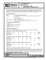
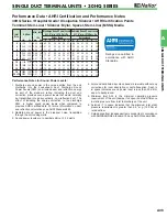
Model 30RE
Electric Coil Limitations
*
Minimum required airflow must be the greater of the air volume listed or 70 cfm per kilowatt (33 L/s/kW)
Unit
Size
Heating Range*
cfm (l/s)
Maximum kW
Single Phase
Three Phase
120V 208V 220V 240V 277V 347V 208V 380V 480V 600V
4
5
6
25 – 225 (12 – 106)
45 – 400 (21 – 189)
65 – 550 (31 – 260)
3.0
5.0
5.5
3.0
5.0
7.5
3.0
5.0
7.5
3.0
5.0
7.5
3.0
5.0
7.5
3.0
5.0
7.5
3.0
5.0
7.5
3.0
5.0
7.5
3.0
5.0
7.5
3.0
5.0
7.5
7
8
9
95 – 800 (45 – 378)
125 – 1100 (59 – 519)
165 – 1400 (78 – 661)
5.5
5.5
5.5
9.5
9.5
9.5
9.5
10.5
10.5
9.5
11.0
11.0
9.5
13.0
13.0
9.5
13.0
16.0
9.5
13.0
16.0
9.5
13.0
16.0
9.5
13.0
16.0
9.5
13.0
16.0
10
12
14
215 – 1840 (101 – 868)
290 – 2500 (137 – 1180)
360 – 3125 (170 – 1475)
5.5
5.5
5.5
9.5
9.5
9.5
10.5
10.5
10.5
11.0
11.0
11.0
13.0
13.0
13.0
16.5
16.5
16.5
17.0
17.0
17.0
16.5
16.5
16.5
21.0
30.0
31.0
21.0
30.0
38.5
16
24 x 16
430 – 3725 (203 – 1758)
960 – 8330 (453 – 3931)
5.5
5.5
9.5
9.5
10.5
10.5
11.0
11.0
13.0
13.0
16.5
16.5
17.0
17.0
16.5
16.5
31.0
31.0
38.5
38.5
• Primary auto-reset high limit thermal cut-out.
• Secondary manual reset high limit thermal cut-outs (one per
element).
• Positive pressure airflow switch.
• Derated high quality nickel-chrome alloy heating elements.
• Magnetic or safety contactors and/or PE switches as required.
• Control transformer. Class II, 24 Vac for digital and analog
controls.
• Line terminal block.
• ETL Listed as an assembly.
• Hinged door control enclosure.
• High performance arrowhead insulators.
• Slip and drive discharge connection.
• Class A 80/20 Ni/Cr wire.
Options:
• Quiet contactors.
• Mercury contactors.
• Toggle type disconnect switch.
• Door interlock disconnect switch.
• Power circuit fusing.
• Dust tight construction.
• SCR control.
Tested and approved
to the following
standards:
ANSI/UL
1996, 4
th
ed.
CSA C22.2
No. 155-M1986.
Standard Features: