background image

S3600 Series Installation Guide

Initial Startup after Power on of Switches

NADDOD Pte. Ltd.

19

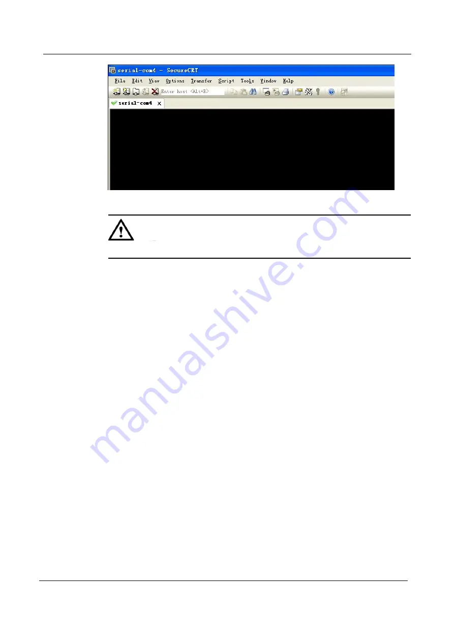
Figure 3-9

Serial Port Display Window

CAUTION

Please use the attached DB-9 to RJ-45 cable to avoid incompatibility.

3.4 Power on of Switch

After power on of switch, the terminal shows device self-checking information, and the

system turns to cmd (such as
switch#) after self-checking is completed.
Type in commands to configure Ethernet switch or view running status of Ethernet switch.

You can type in “?” at any time if you need help.
Please consult the command line reference or configuration guides for detailed configuration

commands.

Summary of Contents for S3600 Series

Page 1: ...NADDOD S3600 Series Ethernet Switches Installation Guide...

Page 2: ...com Customer complaint hotline 400 0698 860 Address of headquarters of the Company 302 Building F1 Optics Valley Software Park Guanshan 1st Road East Lake High tech Zone Wuhan P R China Postcode 43000...

Page 3: ...X S3600 48S4X Stipulations Symbol Stipulations The following symbols may appear in the document of which the meanings are as below Symbol Description Text marked with this symbol means potential risk...

Page 4: ...Song The main body is in Song Gothic Level 1 title Level 2 title Level 3 title and Block are in Gothic Regular Warnings and hints are in Regular Lucida Console Lucida Console format indicates screen o...

Page 5: ...Port Indicator 13 1 5 4 10 100 1000BASE T Self adapting Ethernet Port Status Indicator 13 1 5 5 SFP Port Status Indicator 14 1 5 6 SFP Port SFP Port Status Indicator 14 2 Installation Guide 6 2 1 Prep...

Page 6: ...19 4 Technical Data 20 4 1 Overall Parameters 20 5 Switches System Software Loading 21 6 Switches Operating System Upgrade 23 7 Maintenance and Troubleshooting 25 7 1 Troubleshooting of Load Failure 2...

Page 7: ...and are of rich security features NADDOD S3600 Series Switches are flexible for networking and easy to maintain and are widely applied for aggregation or access of large and medium scaled campus netwo...

Page 8: ...l interface 4 SFP port status indicator 5 USB port 6 Ethernet management port 7 CONSOLE port 8 System status indicator SYS 9 System power status indicator PWR 10 10G SFP port 11 10G SFP port status in...

Page 9: ...ram of S3600 24T24S4X Back Panel 1 Grounding screw 2 Expansion slot 1 3 Expansion slot 2 4 Pluggable fan 1 5 Pluggable fan 2 6 Pluggable power supply 1 7 Pluggable power supply 2 1 3 2 S3600 48S4X Fig...

Page 10: ...types include 10G SFP optical interface the supported SFP optical module type 10GBASE X 1G SFP optical interface the supported SFP optical module type 1000BASE X Downlink port S3600 24T24S4X 48 24 10...

Page 11: ...Properties of 10 100 1000M Ethernet Electrical Interface Property Description Connector type RJ45 Operating mode Support 10 100 1000M rate adaption Support full duplex half duplex auto negotiation MD...

Page 12: ...ement Port S3600 series switches integrate out of band management Ethernet interface and the interface is 1000Base TX or 100Base T It is recommended to use the attached cables which are generally used...

Page 13: ...h file system of switches such as uploading or downloading application files etc NOTE Considering the discrepancies in the compatibility and driving of USB devices from different manufacturers NADDOD...

Page 14: ...Indicator name Status Description MGMT Green Always on 1000M port link up Flash The port is sending or receiving data packets Yellow Always on 10 100M port link up Flash The port is sending or receiv...

Page 15: ...24T24S4X Yellow Flash The 1G port is sending or receiving data packets Yellow Always on 1G port link up Off The port is not linked up 1 5 6 SFP Port SFP Port Status Indicator Table 1 13 SFP Port SFP P...

Page 16: ...hes can works normally with correct voltage only Please confirm that the operating voltage is consistent with the voltage marked on the switches To lower the risk of electric shock please don t open t...

Page 17: ...eing of insulating materials to lower the reliability of switches and largely reduce the service life Table 2 1 Temperature and humidity Item S3600 24T24S4X S3600 48S4X Working condition temperature 0...

Page 18: ...terference The work site of switches must keep far away from high power radio transmitting station radar transmitting station or high frequency strong current equipment Measures for electromagnetic sh...

Page 19: ...e 2 1 Schematic Diagram of Front Suspension Loop Description 1 Screw hole for fixing the front suspension hoop and chassis 2 Screw hole for fixing the front suspension hoop and switch CAUTION The fron...

Page 20: ...install one end of the front suspension loop onto switch as shown in Figure 2 3 Figure 2 3 Schematic Diagram of Front Suspension Loop Installation Step 4 Horizontally place switch on the tray gently...

Page 21: ...ssis The common practice in such case is to place switch on a clean workbench This is simple and only the following matters must be kept in mind The workbench must be stable and grounded properly A sp...

Page 22: ...and push in the power module smoothly along the power supply socket until the power module completely connects with the underpan Step 4 Fix the power supply onto the switch via the power fixing devic...

Page 23: ...be enhanced Correct grounding mode Connect one end of the green yellow protective grounding cable of switch to the grounding terminal of switch and the other end to the wiring terminal on the groundi...

Page 24: ...nd Connecting Cables Figure 3 1 Building Local Configuration Environment via Console Port Step 1 Connect the DB 9 hole plug of the provided cable to the serial port of a PC via which switch configurat...

Page 25: ...ple of Windows XP Hyperterminal The method is as follows 1 Go to the hyperterminal window by tapping start program attached communication hyperterminal to create a new connection and the Connection De...

Page 26: ...ol null In other Windows operating systems bps may be expressed as Baud rate data flow control may be expressed as flow control 4 After parameter setting is completed click OK button and the Network H...

Page 27: ...k Properties Interface CAUTION Please use the attached DB 9 to RJ 45 cable to avoid incompatibility 3 3 Setting up Port Parameters SecureCRT Step 1 Install SecureCRT software on PC Step 2 Setting up S...

Page 28: ...se a serial number for PC an example of COM4 Figure 3 8 Serial Parameter Settings Serial Number Selection 4 Set Baud rate as 115200 data bits as 8 parity as null stop bits as 1 and flow control as XON...

Page 29: ...4 Power on of Switch After power on of switch the terminal shows device self checking information and the system turns to cmd such as switch after self checking is completed Type in commands to confi...

Page 30: ...s Table 4 1 shows overall parameters of S3600 products Table 4 1 Overall Parameters of S3600 Series Item Parameters Outline dimension mm S3600 24T24S4X 440 W 460 D 4 4 H S3600 48S4X 440 W 360 D 4 4 H...

Page 31: ...hz data rate Board descriptor tuple not found in eeprom using defaults DRAM 1 GB Clearing DRAM done Flash 2 GB BIST check passed Net octeth0 octeth1 Press ctrl b to stop autoboot 3 Press Ctrl b to ent...

Page 32: ...on the PC serving as server and set the catalogue for files to be loaded assuming the uBoot file to upgraded as u_boot_v1 0 bin Run the command upgrade_uboot u_boot_v1 0 bin to upgrade uBoot here the...

Page 33: ...witch use the command copy to copy the software image on TFTP server to the folder boot of switch Flash Switch copy mgmt if tftp 10 10 29 160 SwitchOS ma v3 1 12 it r bin flash boot SwitchOS ma v3 1 1...

Page 34: ...the switch after reboot next time you can use the command show to view whether the setting is correct Switch show boot images System image files list Current boot image version 3 1 12 Create Time Vers...

Page 35: ...g wrong IP addresses of Server or Switch or wrong loader software name or failure to designate correct operating path of correct TFTP server when using TFTP protocol If you fail to load without physic...

Page 36: ...o information or random codes if the configuration system goes wrong 7 5 Troubleshooting of Terminal No show Fault If the configuration terminal shows no information after power on run checks as follo...

Reviews: