ElectricalInstallationManualU-30“D”Control
www.NabcoEntrances.com
Part #C-00121
Rev. 8-25-16
7-26
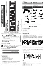
ElectricLockWiring
Section 7d: U30 with Magnetic Lock
12VDC-COMMON
Auxiliary Output (Open-Collector
)
Sequential
Activatio
n
5Amax.(0-20V), 3.2Amax.(20-30V)
30V(42.4Vpeak)max.
Contact Output (Class2 Load only)
FUNCTION [SLIDING DOOR]
REDUCED OPENING SWITCH
Breakout Detector Sidelite Presence Sensor
Exterior
Activatio
n
HOLDING BEAM
INTERIOR
ACTI
VA
TION
12VDC-(COMMON)
12VDC+
Mode Switch (see Mode SW Usage shown left)
Commo
n
N/
C
N/
O
SQ
OU
T
OU
T.
A
OU
T.
B
OU
T.
C
7
SYMBO
L
BA
62
SLS
M1
H M0
6B
9DC12V 7 61
12 13 14 15 16
No.
11
10
9
8
7
6
5
4
3
2
1
RELATED DEVICES - 1
6P
1 2 3 4 5 6 7 8 9 10 11
16
15
14
13
12
ACTI
VA
TION SIGNA
L
OUTPU
T
SIGNA
L
FULL
Y
CLOSED
OPENING
FULL
OPEN
CLOSING
FULL
Y
CLOSE
D
OUTPUT
: 0 = ELECTRIC STRIKE OUTPU
T
OUTPUT
T
IMER
0
=
(DO NOT
USE)
1
=
(DO NO
T
USE)
2
=
(DO NOT
USE)
3
=
ELECTRIC STRIKE FUNCTION
U30 ELECTRIC STRIKE OUTPUT
SIGNA
L
HAND
Y
TERMINAL:
AUX OUTPUT
= 0, OUTPU
T
TIMER = 0, 1 or 2, ROCKER SWITCH SETTING: ONE
WA
Y
OR NIGHT
MOD
E
OUTPU
T
TIMER
1.0
SEC
3 SEC
ON
ON
OF
F
OF
F
120
VA
C
LABE
L
ON U30 CONTRO
L
BLACK (HOT)
SCREW
T
O HEADE
R
WHITE (COMMON
)
GROUND LU
G
ON/OF
F
POWER SWITC
H
TRANSFORMER
A M P
5
TB1
NOISE FI
LT
ER
TB2
T1
S1
NR2
NR
1
AUXILIAR
Y
120
VA
C
POWER WIRE
S
(THESE WIRES NORMALL
Y
COILED
A
ND
TIED UP)
GROUND HARNESS P/N 14-1
1872
VIOLE
T
GR
AY
(OUT
B
)
TERMINA
L
ON U30 MAIN HARNES
S
P/N 24-1
1877
WIRING FOR ELECTRIC LOCK ONL
Y
SHOWN
BLACK
RE
D
RE
D
BLACK
BLACK
BLUE
BROW
N
WHIT
E
Some magnetic locks (as well other types of locks) require a voltage suppression device such as a diode
or MOV. Connect here if needed
.
Read the instructions provided with the lock for details
.
POWER SU
PPLY
14-14299
MAGNETIC LOC
K
>PO
M<
N
A
B
C
O
G
YRO
T
EC
H
D
S
-1
50
0
D
24
-11
32
70
N
ab
te
sc
o C
or
po
ra
tio
n
M
AD
E
IN
JA
PA
N
N
A
BC
O
N
A
B
CO
CAUTION
!
RELATED DEVICE
S
・
16P
12 13 14 15 16
No
.
11
10
9
8
7
6
5
4
3
2
1
SYMBOL
H M0
9DC12V
SQ
OU
T
Common
N/
C
N/
O
OUT. A OUT. B OUT. C
7
BA
62
SLS
M1
6B
7 61
A
Auxiliary Output (Open-Collector
)
5Amax.(0-20V), 3.2Amax.(20-30V
)
30V(42.4Vpeak)ma
x
Contact Output (Class2 Load only
)
12VDC-(Common)
FUNCTION (SLIDING DOOR
)
Reduced Opening Switch
Breakout Detecto
r
Sidelite Presence Sensor
Exteri
or
Holding Beam
Interior
n
12VDC-(Common)
12VDC
+
HANDY
TERMINAL
6P
No.
248901-
Microprocessor Controller
Mode SW Usage
Gn
d
Gn
d
Gn
d
Open
Open
Open
Gn
d
Open
M0
M1
MODE
TWO
WA
Y
ONE
W
AY
NIGH
T
HOLD OPEN
To protect against risk of Fir
e
or electric shock,use only the
WARNING
MOTOR 12
P
ERROR
POWE
R
BA
62
H
6B
61
INDICATORS
POWER
2P
Do not disassemble the control box. There are no user serviceable parts
inside.
To
maintain warranty,
repairs must be
made by authorized NABCO facilities.
Adjustments to the door can only be made with the NABCO Handy T
erminal
.
20VA
C 50/60Hz
GYRO TECH
NABC
O
!
!
!
!
12
11
10
9
8
6
4 3 2
1
7
0
7
5
POWER SUPPLY HARNESS P/N 14-11874
POWER SUPPLY P/N 14-11741
MOTOR/OPERATOR
P/N 24-11327
U30 MICROPROCESSOR CONTROL
P/N 24-8901-30
1 2 3 4 5 6 7 8 9 10 11
16
15
14
13
12
A
C115V±10% 50/60 Hz
U
30
WITH
M
AGNETI
C LO
CK
NO
TE
: LO
CK
W
ORKS
O
NL
Y
IN
N
IGH
T
MODE
&
EXIT
M
OD
E
DN 1370