background image

Magnum 4A Control Wiring and Adjustment Manual 

www.NabcoEntrances.com

Part #C-00084 

Rev. 9-09-16

3-8 

Magnum 4A Board Terminals

Table #-1 

Terminal Block Connections

Pole Wire Harness

Circuit

Description

1

Brown

Aux Pwr

24 VAC Neutral


X

Circuit is used for any Sensor that operates on 24 VAC.


X

Sensor must not exceed 0.5 amp current draw.


X

If Sensor exceeds 0.5 amp current draw Fuse (F1) will trip. A 

separate power supply must be used.

2

Orange

24 VAC Hot

3

Violet

Terminal

Continuous Safety


X

Circuit is used with door mounted Sensors on Pull side of door:


X

When Pin (3) is shorted to Pin (5) Sensor will:

•  Stop door during opening

•  Prevent door from moving when door is fully closed


X

Circuit is always active.

4

White

Safety w/Lockout


X

Circuit is used with Header mounted Presence Sensors or Mats 

on pull side of door.


X

When Pin (4) is shorted to Pin (5) Sensor or Mat will:

•  Prevent door from opening if already closed

• 

Hold door open if already open


X

Circuit is only active while door is fully closed or fully open.

5

Red

Signal Common

This Terminal is the Common to activation, safety, back check and 

latch check switches.

6

Black

Activation

Circuit is used for activation of door. When Pin 6 is shorted to Pin 5 

door is activated.

Table #-2 

Switch Harness

Pin

Wire

Circuit

Description

1

Orange

Door Closed 

Door closed or Latch check signal

2

N/A

N/A

N/A

3

Red

Common

Common for Check Signals

4

Blue

Back Check

Door open or back check signal.

Section 3b. 

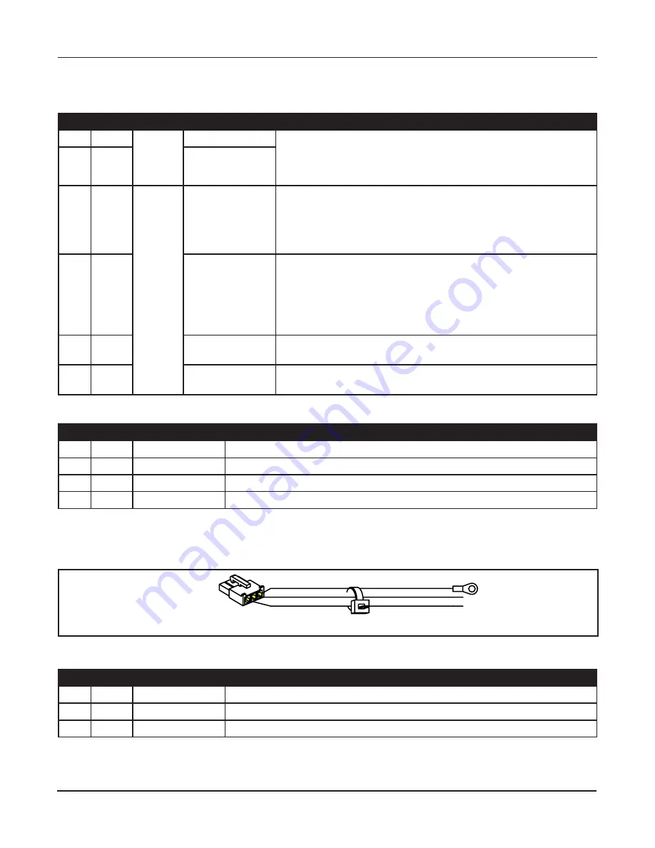
Power Harness

The 120 VAC Power Connector Harness is connected to J4. Please se e Figure 3-3

.

Figure 3-3 

Power Harness

DN 0606

1

Table #-3 

Power Connector Harness

Pin

Wire

Circuit

Description

1

Green

120 VAC

Incoming Ground wire

2

White

120 VAC

Incoming Neutral wire

3

Black

120 VAC

Incoming Hot wire

Summary of Contents for GT 300

Page 1: ...rrective action can be achieved by a NABCO trained technician Failure to follow these practices may result in serious consequences NEVER leave a Door operating without all Safety detection systems operational Swing Door Operator Wiring and Adjustment Manual with Magnum 4A Control DN 0557 LED TRANSFORMER AUX PWR J2 J5 AC IN SW2 SW1 F1 RELAY RELAY J4 TDAS SIGNAL INPUT TDPG LCHK CLOSE Fuse 1 0 5A 24 ...

Page 2: ...ONNECT INCOMING 120 VAC WIRES 5 15 CHAPTER 6 WIRING SAFETY DEVICES 6 16 Section 6a Panic Breakout Latch Switch Open Loop Continuous Safety Circuit 6 16 Section 6b Panic Breakout Latch Switch Closed Loop Continuous Safety Circuit 6 17 CHAPTER 7 WIRING DIAGRAMS GENERAL 7 19 Section 7a GT 300 400 500 Single Door 7 19 Section 7b GT 300 400 500 Simultaneous Pair 7 20 Section 7c GT 300 400 500 Simultane...

Page 3: ...ould not be considered for property damage unless personal injury risk is present Indicates a hazardous situation which has some probability of severe injury It should not be considered for property damage unless personal injury risk is present Indicates a hazardous situation which may result in a minor injury Caution should not be used when there is a possibility of serious injury Caution should ...

Page 4: ...th all applicable governing agency codes Do not place finger or uninsulated tools inside the electrical controller Touching wires or other parts inside the enclosure may cause electrical shock serious injury or death The Ground wire from the Opus Control 120 VAC Harness and the Incoming 120 VAC Ground wire must be connected to the Ground screw located within the Swing door Header Do Not touch othe...

Page 5: ...oors and ANSI Standard 156 19 Used to cover Low Energy doors apply Other local standards or codes may apply Use them in addition to the ANSI standards The owner should determine the door is operating properly and should immediately call for service if there is any malfunction All installation changes and adjustments must be made by qualified NABCO trained technicians Section 1b Objective The Opus ...

Page 6: ...puts with programmable functionality for air curtains or other devices Power Close and Hold Close built in Recycle on object detection during Opening cycle with all motors Recycle on object detection during Closing cycle with encoder motors Full Power or Low Energy application capability Works with the current U Series Rocker Switches Section 2b Electrical Specifications All Wiring Diagrams includ...

Page 7: ... 10 Control must not exceed 500mA 0 5 amps when outputting power to Sensors Modules Accessories Auxiliary Equipment If TOTAL current draw exceeds 500 mA 0 5 amps the installer must utilize an auxiliary power supply such as the NABCO Transformer 24 VAC P N 14 2101 The Opus 10 Control must Not be used to output power to Magnetic Locks Electric Strikes To determine if an auxiliary power supply must b...

Page 8: ...se Non Replaceable N A F2 Not Rese ableFuse N A LED TRANSFORMER AUX PWR J2 O F F 12 4 3 J5 AC IN SW2 SW1 F1 RELAY RELAY J4 TDAS SIGNAL INPUT TDPG LCHK CLOSE Fuse 1 0 5A 24 VAC STOP OPEN BCHK CURRENT LIMIT MOTOR J1 R28 MAGNUM 4A F2 Fuse 2 5A120 240 Capacitor MOV F2 Section 3a Main Harness The Main Harness is used on both a Full Automatic door and Low Energy door Wiring consists of 3 Connecting Harn...

Page 9: ...ed Presence Sensors or Mats on pull side of door X X When Pin 4 is shorted to Pin 5 Sensor or Mat will Prevent door from opening if already closed Hold door open if already open X X Circuit is only active while door is fully closed or fully open 5 Red Signal Common This Terminal is the Common to activation safety back check and latch check switches 6 Black Activation Circuit is used for activation...

Page 10: ...Outputs power from J5 Motor Feed Terminal to Motor Leads X X Slows door down if Brake Module Connector is accidently unplugged from J5 Section 3d Motor Harness 710 8310 8710 Figure 3 5 Motor Harness 710 8310 8710 DN 0597 Connector plugs into J5 Motor Leads Motor Input J5 Motor Connector LED TRANSFORMER AUX PWR J2 O F F 12 4 3 J5 AC IN SW2 SW1 F1 RELAY RELAY J4 TDAS SIGNAL INPUT TDPG LCHK CLOSE Fus...

Page 11: ...0 from fully closed Latch Check 10 from fully closed to fully closed Section 4b Adjustments Adjustments to the Magnum 4A Control can be made using the Dip Switch SW1 or the the Potentiometer 1 8 or the Slide Switch SW2 DN 0560 Adjustment Poten ometers Dip Switch SW1 SW2 R2 R3 R4 R5 R6 R7 R8 TDAS TDPG LCHK CLOSE STOP OPEN BCHK CURRENT LIMIT R28 LED O F F 12 4 3 SW1 Slide Switch SW2 4 b a Dip Switch...

Page 12: ... X X Door will open time out and then close Off Sequential Mode X X One activation opens door second activation closes door Door will not work if dipswitch 2 is OFF without a closed circuit between terminals 5 4 and 5 3 The Red LED will also blink 4 b b The Slide Switch SW2 The Slide Switch is used to select Operator mode during motor operation These two modes are Upper Position Used for Low Energ...

Page 13: ...the on off hold open switch to hold open 3 After the door has been in the back check area for 8 seconds motor power will be reduced according to the STOP setting If the door begins to slowly drift close turn the STOP potentiometer slightly clockwise to increase power 4 Turn On Off Hold Open switch off and allow the door to time out and fully close 5 Turn the On Off Hold Open switch to hold open ag...

Page 14: ...the fully closed position once the door is manually pushed out of latch position X X If Push n Go is desired for all door positions a clutchless operator must be ordered The GT 710 uses a Direct Drive and that is equavelent to a clutchless operator LCHK Latch Check Adjustment Not used on 710 8310 8710 Sets Latch Check speed from last 10 of sweep to the full closed position Full Automatic door 1 5 ...

Page 15: ... display what the Magnum 4A Control is reacting to at any instant within the Swing door cycle This helps to identify when the Swing door system is functioning properly Please see Figure 4 4 Figure 4 4 LED Indicators DN 0558 Red LED Green LED LED TRANSFORMER AUX PWR J2 F1 TDAS SIGNAL INPUT TDPG LCHK CLOSE Fuse 1 0 5A 24 VAC STOP OPEN BCHK J1 Table 4 3 Status LED Indicators LED Status Description Gr...

Page 16: ...ce Access Hole located at the left or right side of Header End Cap a It is recommended for the Installer to house all Incoming 120 VAC wires within an Electrical Conduit Keep all Incoming 120 VAC wiring separate from low voltage wiring within Header 4 Obtain self sticking white plastic Wire Clips that were provided within Header 5 Pull off backing of each Wire Clip to expose adhesive Adhere each W...

Page 17: ...en the door is broken out When door is broken out the Panic Breakout Switch CLOSES the circuit to activate the Continuous Safety feature and disable the Operator 1 Turn OFF Power 2 Go to Panic Latch located at bottom of Header 3 Ensure that the EXT arrow points to the Interior side of the building Panic Breakout Limit Switch will CLOSE when door is broken out Please see Figure 6 1 DN 0060 EXT INTE...

Page 18: ...1 REL AY REL AY J4 TDAS SIGNAL INPUT TDPG LCHK CLOSE Fuse 1 0 5 A 24 VAC STOP OPEN BCHK CURRENT LIMIT MOTO J1 R28 MAGNUM 4A R Fuse 2 5 A120 240 Capacitor MOV 11 Go to ends of each Red wire connected to Panic Latch Harness Cut white plastic connectors off Please see Figure 6 4 12 Strip all wire ends 1 4 inch Figure 6 4 Cut off Panic Latch Harness Connectors DN 0565 EXT 13 Go to the 6 Pole Terminal ...

Page 19: ...2 3 5 6 To Magnum Control Safety with Lockout during door swing To Terminal 5 Normally Closed Contacts Continuous Safety Normally Closed Contacts Red Red Part 11 0941 Panic Latch Kit TERMINAL BLOCK 1 BROWN 2 ORANGE 3 VIOLET 4 WHITE 5 RED 6 BLACK 24VAC NEUTRAL 24VAC HOT CONTINUOUS SAFETY SAFETY WITH LOCKOUT ACTIVATION When using normally closed safety all panic breakout devices connected to continu...

Page 20: ...Activation Signals to Terminals 5 and 6 Directly Part 10 3528 RS 12 Rocker Switch Red Red Part 11 0941 Panic Latch Kit When the unit has Panic Breakout feature Breakout Limit Switch Signal and or Panic Latch Signal MUST be connected to Continuous Safety input Terminal Block 3 5 Breakout Limit Switch N O Black and Brown Latch Check Limit Switch Part 22 10065 Harness Assy for Single Back Check Limit...

Page 21: ...FETY OUTPUT FROM DOOR MOUNTED SWING SIDE SENSOR Arrow marked EXT points into the building Contacts must close when door is broken out If door can break out black and brown wires from the operator should be connected to terminals 3 and 5 on the main harness OR red wires from the panic latch should be connected to terminals 3 and 5 on the main harness Single red and single orange wires terminals 2 a...

Page 22: ...OR MOUNTED SWING SIDE SENSOR O F F 12 4 3 AUX PWR J2 J5 AC IN F2 SW2 SW1 F1 R2 R3 R4 R5 R6 R7 R8 TDAS TDPG LCHK CLOSE STOP OPEN BCHK CURRENT LIMIT MOTOR J1 R28 MAGNUM 4A LED TRANSFORMER RELAY RELAY J4 SIGNAL INPUT CAPACITOR C26 D10 MOV3 6 5 4 3 2 1 TERMINAL BLOCK 1 BROWN 2 ORANGE 3 VIOLET 4 WHITE 5 RED 6 BLACK 24VAC NEUTRAL 24VAC HOT CONTINUOUS SAFETY SAFETY WITH LOCKOUT 24VAC COMMON ACTIVATION On...

Page 23: ...20 VAC HOT 120 VAC NEUTRAL SERVICE GROUND MINIMUM 5 AMPERE SERVICE PER OPERATOR BLACK GROUND RED WHITE BLACK TO TERMINAL 5 TO TERMINAL 5 GREEN RED BLACK FOR RIGHT HAND OPERATORS MATCH MOTOR WIRES RED TO RED BLACK TO BLACK FOR LEFT HAND OPERATORS MIS MATCH THE MOTOR WIRES RED TO BLACK BLACK TO RED ACTIVATION OUTPUT FROM SENSOR REMOTE RECEIVER PUSH PLATE ETC SAFETY WITH LOCKOUT OUTPUT FROM OVERHEAD ...

Page 24: ... PART 22 10065 MAIN HARNESS BLACK BLACK BLACK GREEN WHITE 120 VAC HOT 120 VAC NEUTRAL SERVICE GROUND MINIMUM 5 AMPERE SERVICE PER OPERATOR BLACK GROUND RED WHITE BLACK TO TERMINAL 5 TO TERMINAL 5 GREEN RED BLACK BLACK RED BLACK BLACK RED BLACK BLACK WHITE WHITE GREEN GREEN FOR RIGHT HAND OPERATORS MATCH MOTOR WIRES RED TO RED BLACK TO BLACK FOR LEFT HAND OPERATORS MIS MATCH THE MOTOR WIRES RED TO ...

Page 25: ...ICE PER OPERATOR 120 VAC NEUTRAL 120 VAC HOT BLACK BLACK BLACK O F F 12 4 3 AUX PWR J2 J5 AC IN F2 SW2 SW1 F1 R2 R3 R4 R5 R6 R7 R8 TDAS TDPG LCHK CLOSE STOP OPEN BCHK CURRENT LIMIT MOTOR J1 R28 MAGNUM 4A LED TRANSFORMER RELAY RELAY J4 SIGNAL INPUT CAPACITOR D10 MOV3 6 5 4 3 2 1 TERMINAL BLOCK 1 BROWN 2 ORANGE 3 VIOLET 4 WHITE 5 RED 6 BLACK 24VAC NEUTRAL 24VAC HOT CONTINUOUS SAFETY SAFETY WITH LOCK...

Page 26: ...T 22 10065 MAIN HARNESS 14 14362 BLACK BLACK BLACK BLACK BLACK BLACK WHITE GREEN GREEN WHITE WHITE 120 VAC HOT 120 VAC NEUTRAL SERVICE GROUND MINIMUM 5 AMPERE SERVICE PER OPERATOR NOTES 1 WIRES AT SENSOR CONNECTORS AND SWITCH CONNECTORS IN THIS DRAWING DO NOT REPRESENT THE ORDER OF THE WIRES AT THAT CONNECTOR 2 SENSORS OR OTHER ACTIVATION DEVICES MUST USE NORMALLY OPEN DRY CONTACTS FOR TRIGGERING ...

Page 27: ...K WHITE GREEN BLACK WHITE BLACK WHITE N C BREAK OUT SWITCHES RED VIOLET ORANGE BROWN MAIN HARNESS SIM PAIR PART 22 10270 TRANSFORMER 14 2101 120 VAC BROWN BLUE WHITE RED FOLD SIDE ACUVISION 14 10823 01 APPROACH SIDE ACUSENSOR 14 8902 FOLD SIDE ACUSENSOR 14 8902 NOTES 1 WIRES AT SENSOR CONNECTORS AND SWITCH CONNECTORS IN THIS DRAWING DO NOT REPRESENT THE ORDER OF THE WIRES AT THAT CONNECTOR 2 SENSO...

Page 28: ...D PART 22 13952 Y HARNESS PART 22 10065 MAIN HARNESS 14 14362 BLACK BLACK BLACK BLACK BLACK BLACK BLACK WHITE GREEN GREEN WHITE 120 VAC HOT 120 VAC NEUTRAL SERVICE GROUND MINIMUM 5 AMPERE SERVICE PER OPERATOR NOTES 1 WIRES AT SENSOR CONNECTORS AND SWITCH CONNECTORS IN THIS DRAWING DO NOT REPRESENT THE ORDER OF THE WIRES AT THAT CONNECTOR 2 SENSORS OR OTHER ACTIVATION DEVICES MUST USE NORMALLY OPEN...

Page 29: ...8743 Spacer 240010 01 Brown Hot Blue Neutral Screw 218754 Transformer Transformer J4 Motor Black Green Ground Screw Cup Washer Black Black White Green wires are 24 volt AC and can be used to power accessary devices motion detectors etc Green Ground Screw Cup Washer White Black Blue Green Green Brown Black with white stripe Red Green Green Brown Tan Green Black C OP 120 240 AUX PWR J2 AC IN F2 F1 R...

Page 30: ...s such as sensors from Terminals 1 and 2 and install an alternate power supply such as a Transformer Motor may be blown Replace motor Safety circuit is activated X X Check to ensure Dip Switch 2 is set correctly X X Ensure safety sensors are not activated GT 710 Activation Circuit may not be properly connected To signal a Door Open command activation devices must provide a Dry Switch closure acros...

Page 31: ...ator from Header 2 Separate motor from operator 3 Inspect couplings for looseness Back Check adjustment on Magnum 4A has no effect Door is not going into Back Check at 80 position X X Pre load operator by correctly installing arm on operator spindle per Hardware Installation manuals X X GT 710 Reposition Back Check magnet GT 710 Back check resistance on Hydraulic closer set too high and motor cann...

Page 32: ... to Terminal Block was to Continuous Safety not Safety w Lockout 1 Rewire Safety Sensor to Safety w Lockout 2 Go to Terminal Block 3 Connect the output of the Sensor to Terminal 5 Red Wire and Terminal 4 White Wire Sensor safety mats holding beams or all other accessories mounted on swing side of door do not function while door is moving Connection of Sensor to Wiring harness was to Safety w Locko...

Reviews: