Chapter 5 Maintenance and Inspection
UD-series Screw Compressor
5.5 Reassembly
5-46
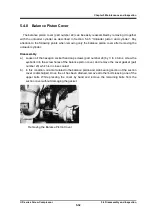
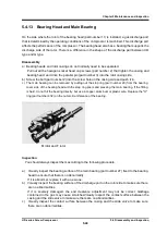
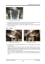
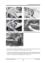
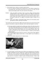
Spring pin of Side Bearing
Setting Retaining Ring of Side Bearing
b
)
After checking that the positioning spring pins and side bearings are in the correct position,
secure the side bearings with the stop ring.
c
)
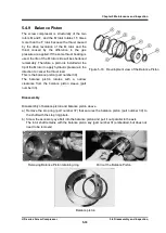
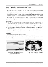
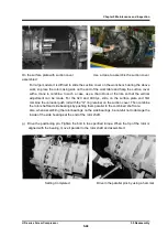
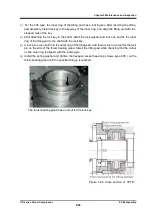
The oil injection pipe and the pipe retainer are fitted with a pin.
This part is installed in the
suction cover. Apply oil to the "O" ring, push it in, and secure with bolts.
Note: There is an oil hole position on the right side when viewed from the unloader cylinder side.
Align the O mark on the right side pipe retainer.
Lubricate the "O" ring of the oil injection
pipe sufficiently.
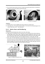
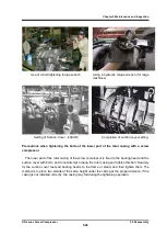
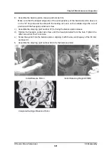
d) Keep the unloader slide valve in the full load position.
Apply oil to the gasket and attach it to
the rotor casing side.
Insert some bolts to prevent it from sliding.
Pull the positioning pin toward
the rotor casing side.
The gasket of the suction cover is asymmetric. Check that it is properly
fitted.
Lubricate the side bearings sufficiently.
For 320 type and 400 type, attach the "O" ring retainer (part number 326) that holds the
unloader push rod to the suction cover.
Don't forget to attach the "O" ring in the hole on the
suction cover body side.
e
)
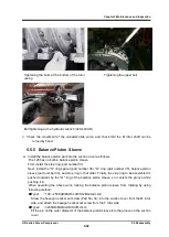
Slide the suction cover over the rotor shaft to align it.
First place the unloader slide valve in the full load position.
Combine the tip of the unloader
pushrod into the oil injection pipe of the suction cover and the unloader pushrod into the injection
pipe.
Be careful not to damage the "O" ring of the injection pipe with the unloader push rod.
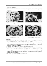
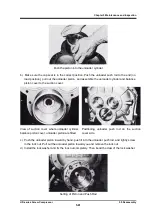
f) Lift the suction cover with a crane and slide it on the workbench. First, combine the unloader
pushrod with the "O" ring retainer of the suction cover.
Next, combine the rotor shaft and side
bearings, and push the suction cover parallel to the shaft core to combine it with the rotor
casing.
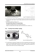
Setting Bearing
Side bearing positioning

