Chapter 5 Maintenance and Inspection
UD-series Screw Compressor
5.5 Reassembly
5-43
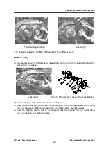
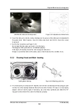
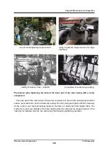
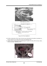
400UD slide valve and bearing head Figure 5-19 Adjustment of Slide Value
b
)
Insert the slide valve into the casing, making sure the groove of the slide valve is aligned with
the guide block. After insertion, move the slide valve back and forth to check the overall
movement.
c
)
Set it to the C position (see Figure. 5-19).
Do not twist the slide valve as shown in A in the figure.
This happens if the guide block is not installed properly.
In the figure, B carefully checks the rotor casing and slide valve.
Sharpen or polish the bottom of the slide valve so that it becomes the condition of (C)
5.5.2
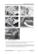
Bearing Head and Main bearing
a
)
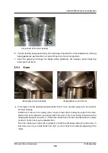
The main bearing is a clearance fit.
Align the notch of the main bearing with the spring pin (part
number 14) of the bearing head and drive with a wooden hammer.
If it slips or is not properly
aligned, remove it and try again.
If necessary, use a tool like a hydraulic jack.
Attach the "O"
ring (part number 432) of the outer circumference properly.
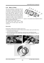
Setting Main Bearing
Figure 5-20 Bearing pull-in too


