Chapter 5 Maintenance and Inspection
UD-series Screw Compressor
5.4 Disassembly and Inspection
5-41
5.4.14 Unloader Slide Valve and Guide Block
The guide block consists of a guide block stem (part number 88), a guide block (part number 87),
and two "O" rings.
The guide block meshes with the slot in the bottom of the slide valve.
The length of this unloader slide valve assembly varies depending on the compressor model.
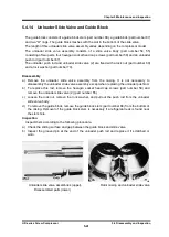
The unloader slide valve assembly consists of a slide valve body (part number 54, 55)
consisting of two parts, four hexagon socket head cap screws (part number 58) and an unloader
push rod (part number 67).
The unloader push rod and unloader slide valve (2) are fixed with a lock nut (part number 69)
and a lock washer (part number 70).
Disassembly
a) Remove the unloader slide valve assembly from the casing.
It is not necessary to
disassembly the unloader slide valve assembly except when replacing the unloader pushrod.
b) To replace this rod, remove the hexagon socket head cap screws (part number 58) and
remove the unloader slide valve (2) (part number 55).
c) Loosen the lock nut, remove the lock washer, and pull out the push rod from the unloader
slide valve body.
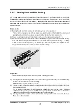
d) To remove the guide block, remove the guide block stem (part number 88) from the bottom of
the casing.
Removal of the guide block stem is necessary if a refrigerant leak is found near
the stem hole.
Inspection
Inspect them according to the following procedure.
a) Check the sliding surface and gap between the guide block and slide valve.
b) Inspect the grooved pin at the end of the unloader push rod and replace it if scratched or
worn.
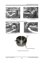
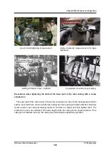
Unloader slide valve assemblies (upper)
、
Rotor casing and unloader slide valve
Disassembled parts (lower)

