MyBinding Plockmatic BM 200 Installation Manual Download Page 19

1-14

31 January 2007

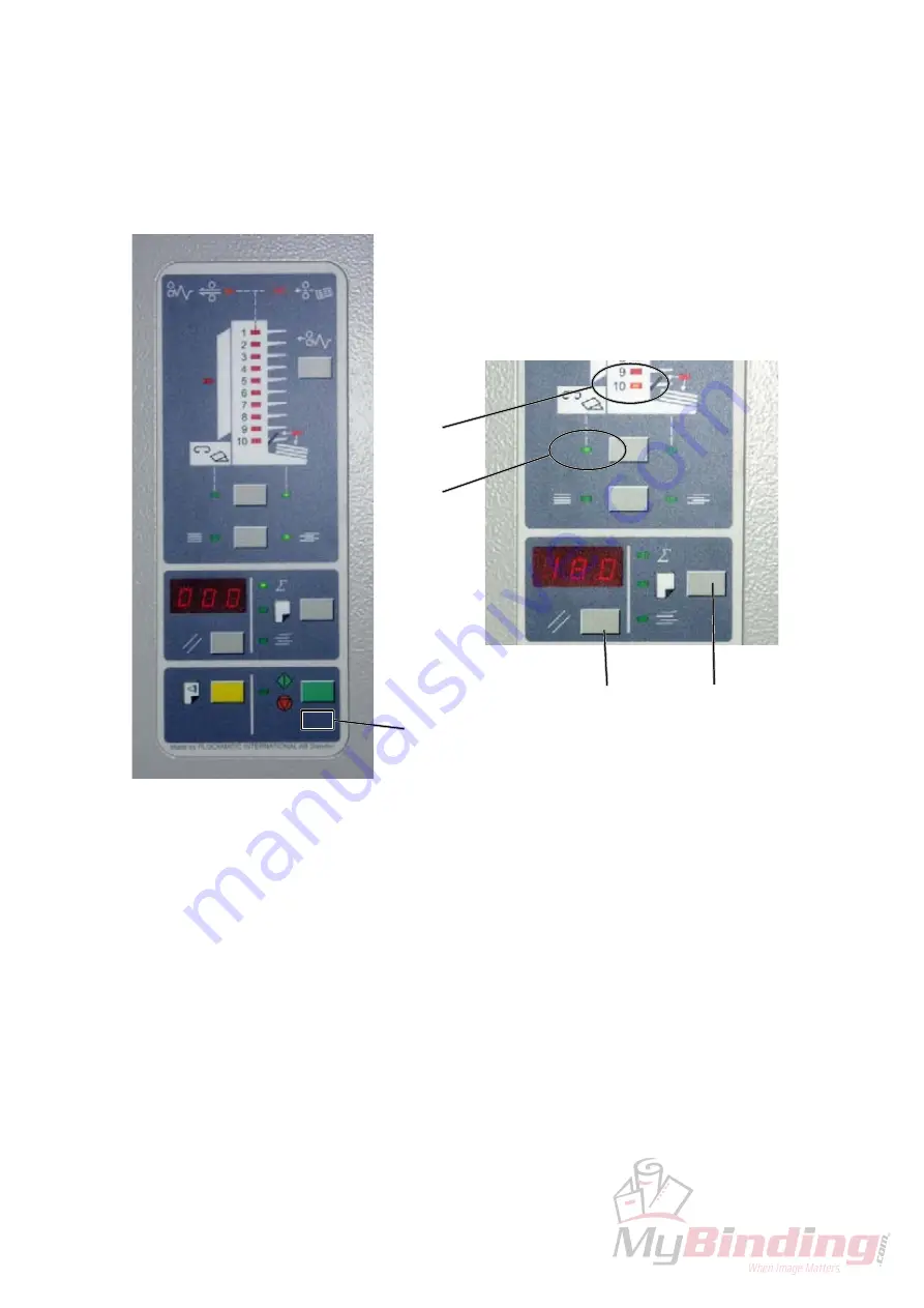
5.  Press button [B] repeatedly until programmable setting No. 20 is displayed. 

This is indicated when bin LED 10 [C] and third party LED [E] on the Colla-
tor display are lit. The correct value for setting No. 20 should read 

180

. If so, 

continue to step 8.

6.  Press button [D] once to display the last digit. Press button [B] to change the 

last digit. 
Press button [D] to display the middle digit. Press button [B] to change the 
middle digit. 

Press button [D] to display the first digit. Press button [B] to change the first 

digit.

7.  Confirm changing setting No. 20 by pressing button [D].

8.  Press hidden button [A] to exit Collator programming mode.

BOOKLET MAKER INSTALLATION

[A]

[D]

[B]

[C]

[E]

Summary of Contents for Plockmatic BM 200

Page 1: ...Provided By http www MyBinding com http www MyBindingBlog com Plockmatic BM200 Booklet Maker Installation Manual...

Page 2: ...pictures within this Installation Instruction are of the right version Due to the mirroring typical Front and Rear designations which normally is viewed from the opera tor location has been replaced b...

Page 3: ...Page intentionally blank...

Page 4: ...uipment grounding conductor can result in electrical shock Always follow all warnings marked on or supplied with the equipment Always locate the equipment on a solid support surface with adequate stre...

Page 5: ...Page intentionally blank...

Page 6: ...TALLATION PROCEDURE 1 1 INSTALLATION REQUIREMENTS 1 1 1 MINIMUM SPACE REQUIREMENTS INSTALLATION REQUIREMENTS SQF 200 FTR 200 BM 200 Stacker 810 mm 31 9 350 mm 13 75 350 mm 13 75 625 mm 24 38 400 mm 15...

Page 7: ...0V AC 50 60Hz More than 2 A 2 Permissible voltage fluctuation 10 3 Never place anything on the power cord INSTALLATION REQUIREMENTS WARNING 1 Make sure that the wall outlet is near the main machine an...

Page 8: ...ok unprofessional because of creep FTR 200 will trim those edges up to 15 mm 19 32 SQF 200 SquareFolder Enables the possibility to give the booklets the perfect bound look Yes No Install the Booklet M...

Page 9: ...Page intentionally blank...

Page 10: ...the following list Description Q ty A Communication Cable 1 B Powercord 1 C Terminator plug will always be installed onto BM 200 1 D Terminator plug FTR 200 1 E Interlock Jumper will always be instal...

Page 11: ...LATION PROCEDURE Unpacking 1 Remove all parts from the pallets 2 Slide the Booklet Maker off the pallet by pulling the two cardboard handles A underneath the Booklet Maker straight out WARNING 2 perso...

Page 12: ...tion and lower the rear end so that the grom mets A and the holes in the guide brackets B are centered towards each other C 2 Secure the rear end of the Upper Top Cover with screws D x2 NOTE After sec...

Page 13: ...ts and the holes in the Top Cover frame are centered towards each other E NOTE There are two guides F and two brackets G on the front side of the Upper Top Cover Make sure that these guides are positi...

Page 14: ...ation 31 January 2007 1 3 3 ADJUSTMENTS BOOKLET MAKER INSTALLATION 1 Remove screws A and remove the Booklet Maker front cover x5 2 Remove screws B loosen screw C and remove the Bookler maker rear cove...

Page 15: ...1 10 31 January 2007 BOOKLET MAKER INSTALLATION 3 Mount the supplied positioning pins on the collator 4 Dock the collator to the Booklet Maker See picture above...

Page 16: ...BOOKLET MAKER INSTALLATION 5 Turn the four adjustment nuts A until the distance B between the lower edge of door and the top of side guide is 3 mm 6 Reinstall the Booklet Maker front and rear covers...

Page 17: ...the Terminator plug D and the Interlock jumper F NOTE Unless Trimmer FTR 200 will be installed If so communication cable and power cord between BM 200 and FTR 200 will be connected 5 Connect the powe...

Page 18: ...ndicated when bin LED 10 C on the Collator display is lit The correct value for setting No 10 should read 120 If so continue to step 5 3 Press button D once to display the last digit Press button B to...

Page 19: ...180 If so continue to step 8 6 Press button D once to display the last digit Press button B to change the last digit Press button D to display the middle digit Press button B to change the middle digi...

Page 20: ...Booklet maker to A4 8 5 x 11 8 Set up the Booklet maker to Staple ON 9 Feed a A4 8 5 x 11 set to the Booklet maker 10 Check for the correct feeding of the set from the Collator NOTE If paper is not f...

Page 21: ...Page intentionally blank...

Page 22: ...on the Trimmer The trim bin is tie wrapped on the rear side Trimmer fan is bubble wrapped and located inside the Trimmer The Rail Extension is located in the packing material Description Q ty A Commun...

Page 23: ...ATION PROCEDURE Unpacking 1 Remove all parts from the pallets 2 Ensure all of the packing material is removed from the outside of the Trimmer 3 Tilt the Trimmer to upright position WARNING 2 persons a...

Page 24: ...anuary 2007 A Remove the Belt Stacker 1 Loosen screws A on the Booklet Maker x 2 2 Disconnect the Belt Stacker cable x 1 3 Remove Belt Stacker from the Booklet Maker 4 Secure screws A x 2 TRIMMER INST...

Page 25: ...1 20 31 January 2007 TRIMMER INSTALLATION 1 Remove the Trimmer front cover by removing the screws A x 5 2 Move the Trimmer up to the Booklet Maker A 1 4 3 ADJUSTMENTS Height adjustment...

Page 26: ...ing bracket B on the Trim mer fits in the docking hole C on the Booklet Maker one revolution on the nuts is 1 5mm 1 16 in height Adjust by turning the four nuts D on the Trim mer with the Multi tool N...

Page 27: ...ry 2007 4 Looking from behind the system make sure that the Trimmer is parallel to the Booklet Maker E 2mm If necessary adjust by turning the two nuts F on the outfeed side of the Trimmer E F TRIMMER...

Page 28: ...cket B x 2 2 Dock the Trimmer to the Booklet Maker 3 Secure the Trimmer by lifting the Locking bracket B and tightening nuts A x 2 NOTE Make sure that the Trimmer locking bracket B locks in the outer...

Page 29: ...1 24 31 January 2007 TRIMMER INSTALLATION Install Trimmer fan 1 Install Trimmer fan A by hanging it onto the position pins B inside the Trimmer A B Trimmer interior towards Booklet Maker...

Page 30: ...cker 1 Loosen screws A x 2 on the Trimmer NOTE Unless the SquareFolder SQF 200 will be installed If so the Belt Stacker will be installed on to the SquareFolder instead 2 Install the Belt Stacker on t...

Page 31: ...le the Trimmer is serviced 6 Connect the communication cable to the Trimmer F x1 NOTE The communication cable you received with the Trimmer 7 Connect the other end of the communication cable to the Bo...

Page 32: ...1 27 Installation 31 January 2007 COM BM 200 COM BM 200 TRIMMER INSTALLATION Continued on next page Trimmer with cable protector installed A C H F L J K...

Page 33: ...1 28 31 January 2007 E G I Booklet Maker rear side Booklet Maker with Trimmer installed TRIMMER INSTALLATION M Cable holder mounted on Booklet Maker Cable holder mounted on Trimmer...

Page 34: ...to INDEX 16 FTR Knife Zero and press the CHG button 9 Key in the value found in the trimmer 10 Go down to Store and press the OK button 11 Remove the two Stapler heads according to section 3 4 12 12 P...

Page 35: ...22 Set up the Collator to send A3 11 x 17 sheets to the Booklet Maker 23 Set up the Booklet maker to A3 11 x 17 24 Set up the Booklet maker to Staple ON 25 Set up the Trimmer to Trimmer ON 26 Feed a A...

Page 36: ...e following list Description Q ty A Communication cable 1 B Power cord 1 C Auto set thickness bracket with spring 1 D Sensor bracket with sensor 1 E Spacer pin and screw 2 F 25 mm washer and screw 2 G...

Page 37: ...FOLDER INSTALLATION 1 Remove all parts from the pallets 2 Ensure all of the packing material is removed from the outside of the Square Folder 3 Tilt the SquareFolder to upright position WARNING 2 pers...

Page 38: ...on the Trimmer 6 Remove the positioning pins from the upper holes B used for the Belt Stacker x 2 7 Using the lower hole C install the Ground strap to the inside of the position ing pin E using the 25...

Page 39: ...A 1 Remove the existing trim bin from the Trimmer This trim bin can not be used together with the SquareFolder 2 Assemble the new extended trim bin A with the four screws and nuts from the installatio...

Page 40: ...stallation 31 January 2007 1 5 3 ADJUSTMENTS Height adjustment SQUAREFOLDER INSTALLATION 1 Remove the front cover of the SquareFolder by removing the screws A x 5 2 Move the SquareFolder up to the Tri...

Page 41: ...the SquareFolder Adjust by turning the four nuts D on the SquareFolder with the Multi tool one revolution on the nuts is 1 5mm in height Adjust on the front and rear side NOTE The Multi Tool is locate...

Page 42: ...rallellity adjustment 4 Looking from behind the system make sure that the SquareFolder is parallel to the Trimmer E 2mm If necessary adjust by turning the two nuts F on the outfeed side of the SquareF...

Page 43: ...lder by lifting the Locking bracket B and tightening nuts A x 2 NOTE Make sure that the SquareFolder locking bracket B locks in the outer slot C on the positioning pin D 4 Install the new Extended tri...

Page 44: ...7 Installing Belt Stacker SQUAREFOLDER INSTALLATION 1 Loosen screws A x 2 on the SquareFolder 2 Install the Belt Stacker on to the SquareFolder 3 Secure the Belt Stacker by tightening screws A x 2 on...

Page 45: ...4 Install the Communication cable D between the Trimmer and the Square Folder x 1 5 Mount the cable protector E positioned as shown with two screws in the holes F and route the cables inside the cable...

Page 46: ...1 41 Installation 31 January 2007 H Cable holder mounted on Booklet Maker Cable holder mounted on Trimmer Cable holder mounted on Square Folder H SQUAREFOLDER INSTALLATION...

Page 47: ...Page intentionally blank...

Page 48: ...with the collar out NOTE Install the Spacer pin s on the rear side of the Booklet Maker 3 Install the Auto set thickness bracket B and tighten it with the other Spacer pin C with the collar in A B C S...

Page 49: ...Sensor bracket by tightening it with the screws B C x 2 torx NOTE Make sure that the Actuator runs in the sensor slot 3 Connect the sensor harness D to the sensor on bracket E x 1 A B C SQUAREFOLDER...

Page 50: ...down to Store and press the OK button 10 Remove the two Stapler heads according to section 3 4 12 11 Perform a Detailed self diagnostic according to section 5 3 3 12 Reinstall the two Stapler heads ac...

Page 51: ...1 x 17 sheets to the Booklet Maker 24 Set up the Booklet maker to A3 11 x 17 25 Set up the Booklet maker to Staple ON 26 Set up the Trimmer to Trimmer ON 27 Set up the SquareFolder to AUTO 28 Feed a 1...

Page 52: ......

Page 53: ......

Reviews: